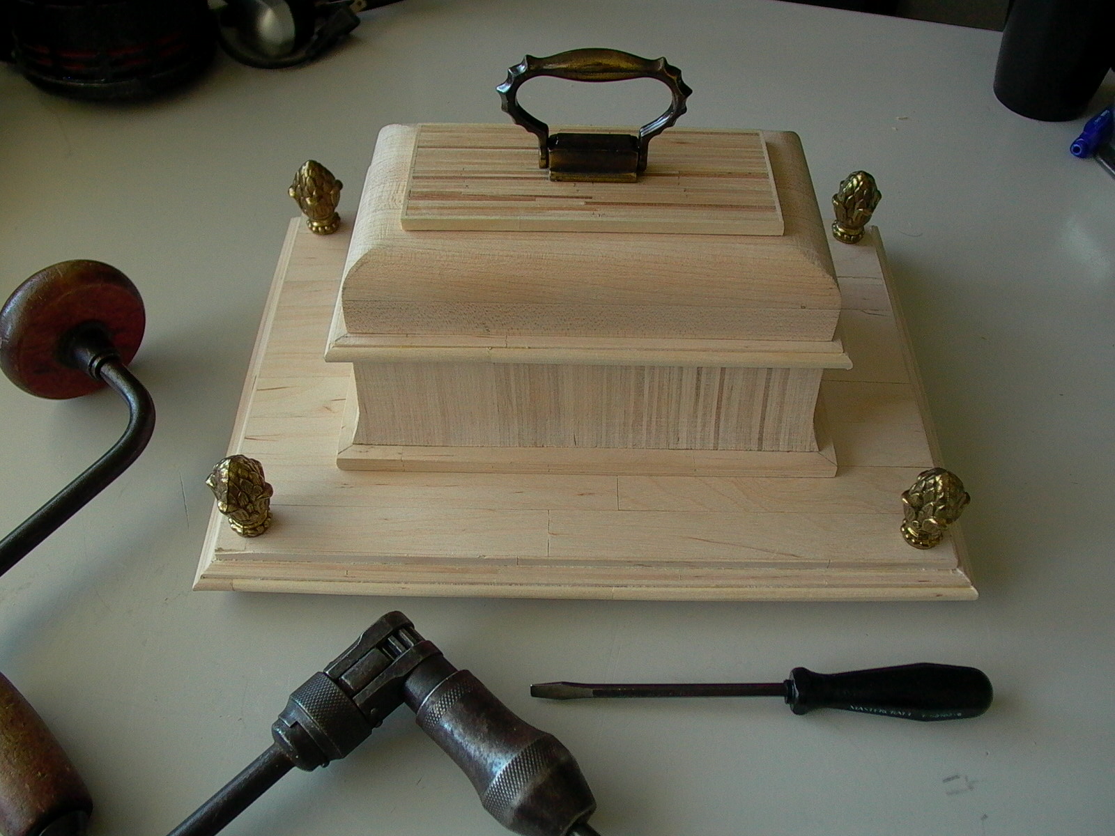
Assembling the Top
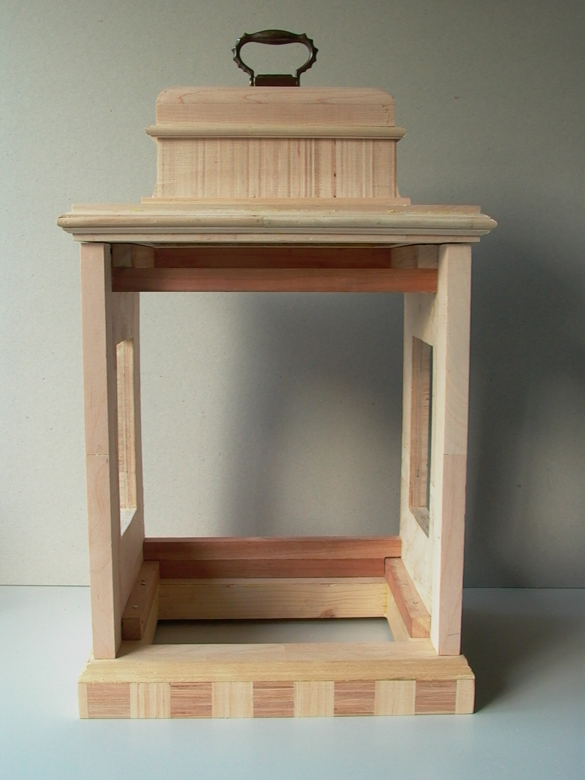
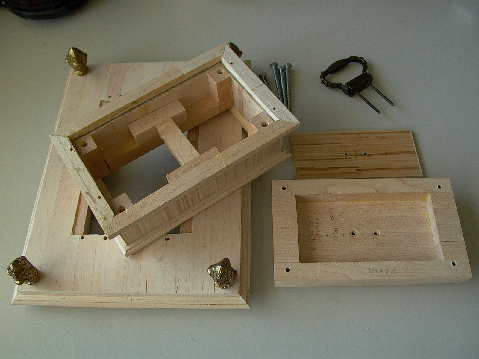
In putting together the top, screws were used instead of nails or glue so that in the future, if I prefer a different design, the top can be easily disassembled and replaced (fig. 100 & 101).
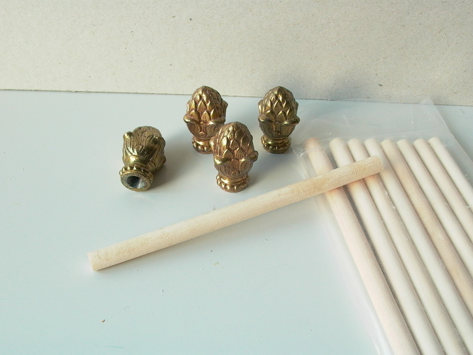
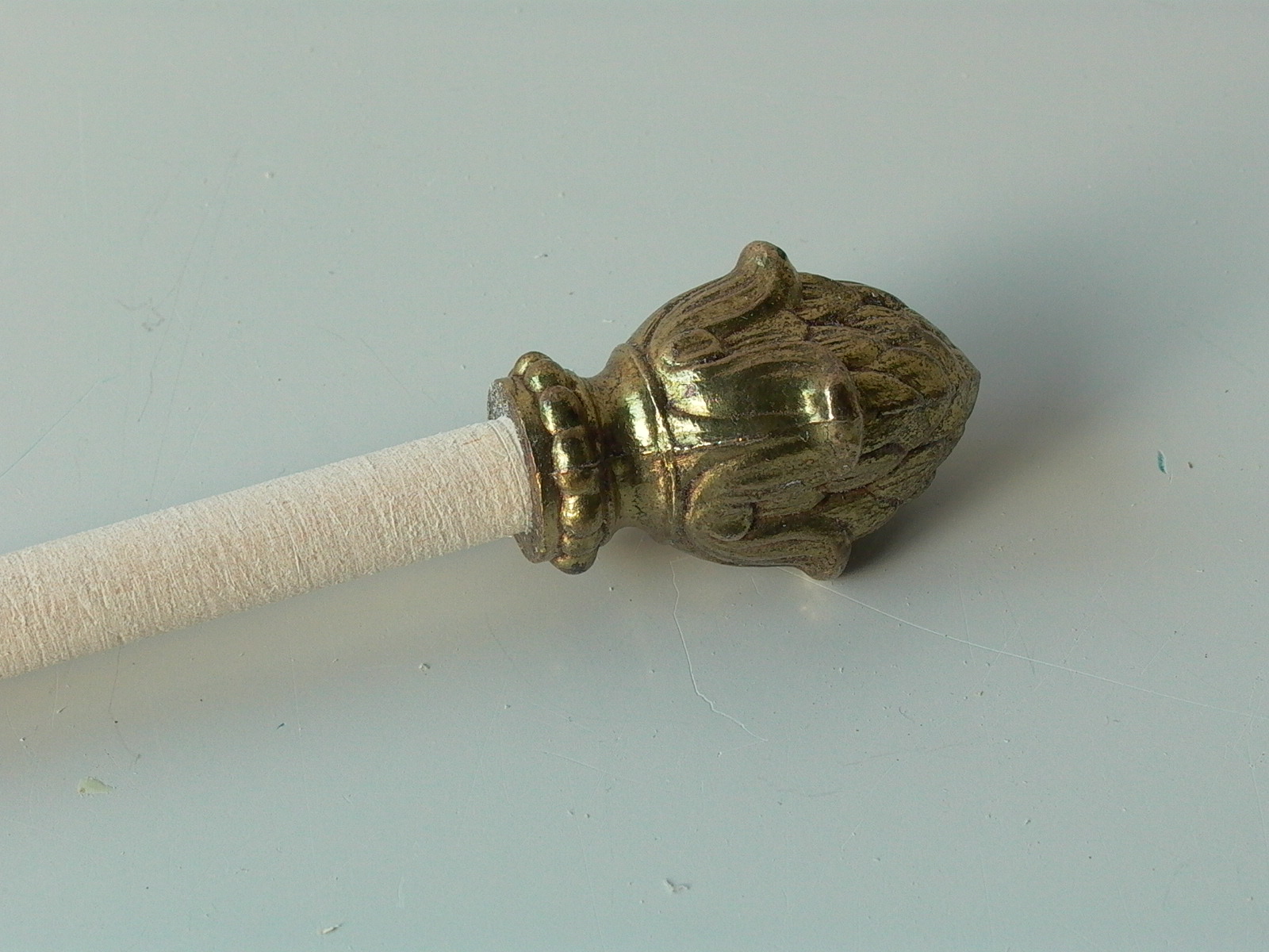
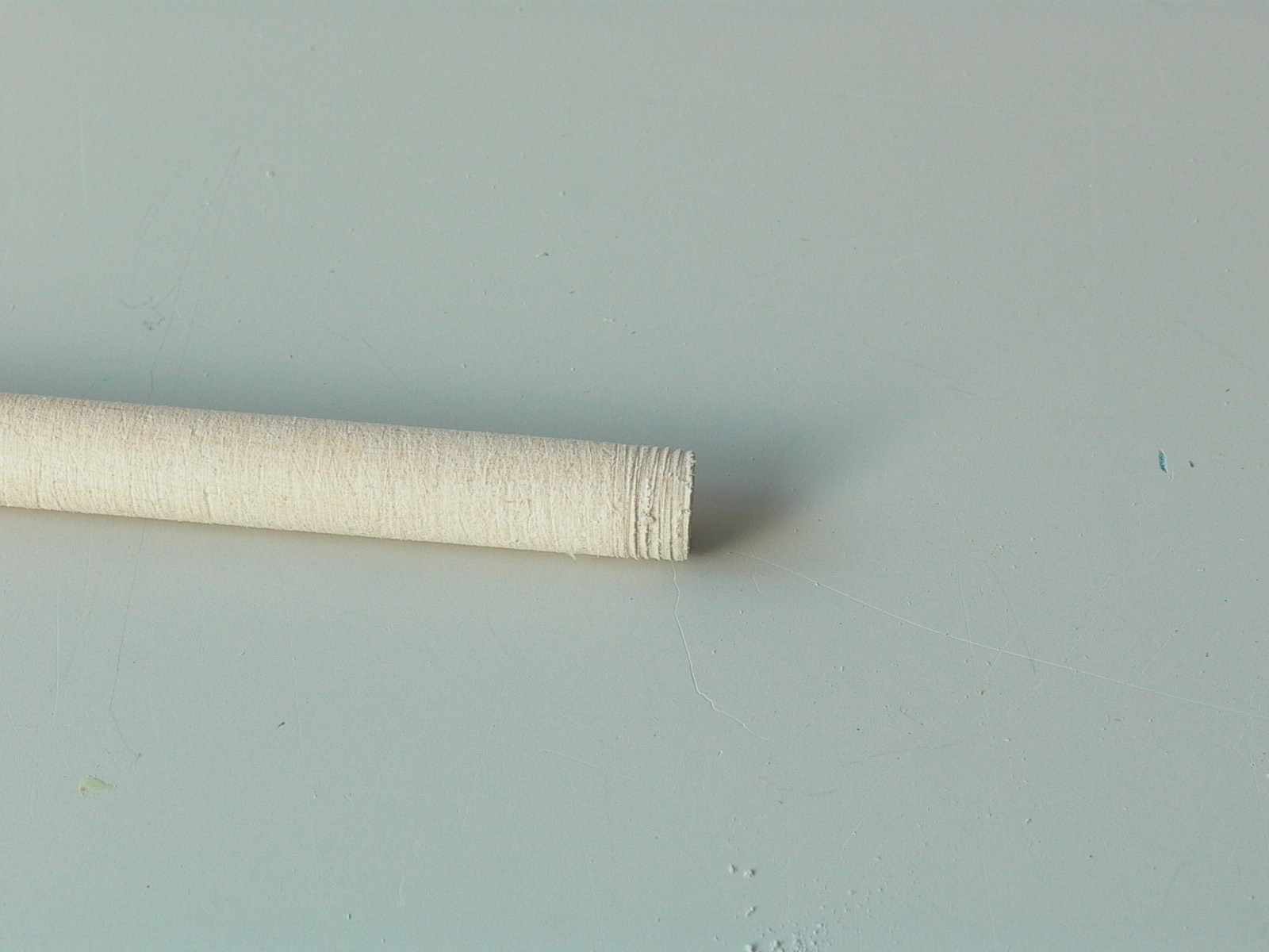
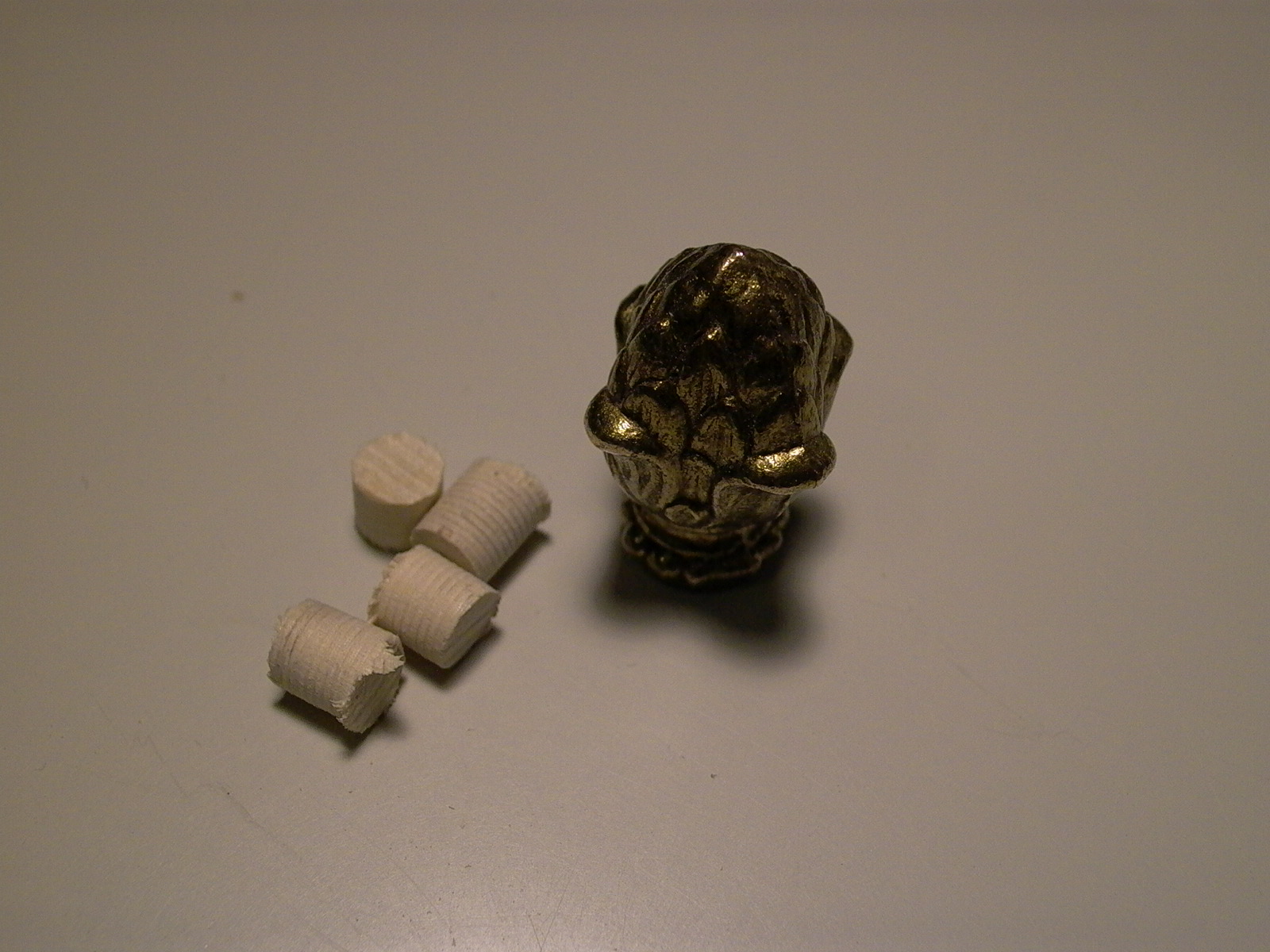
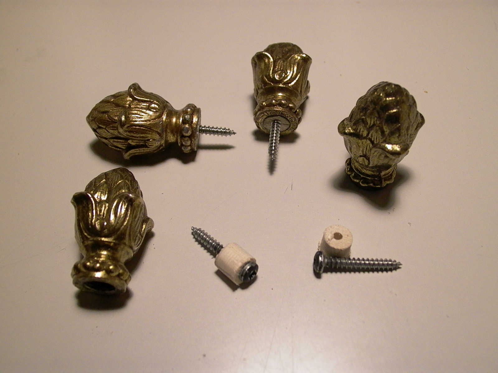
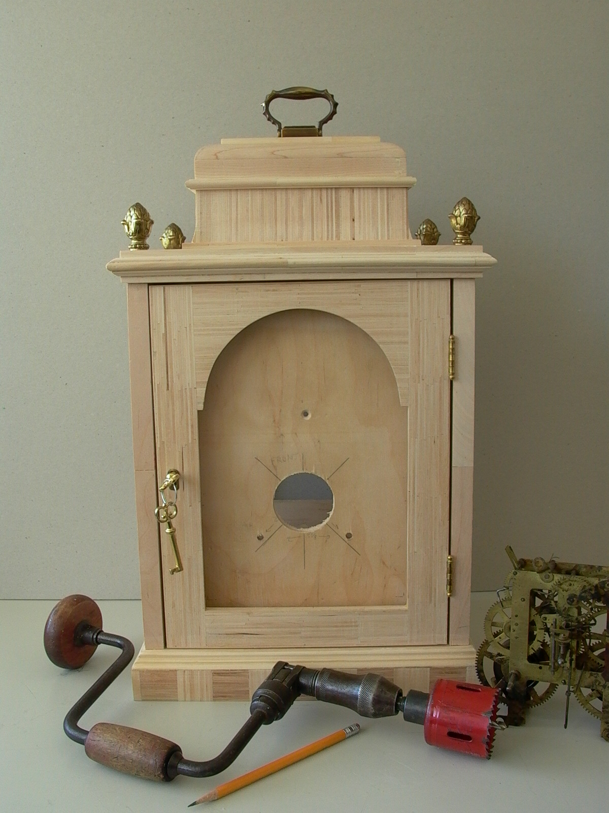
To start off, decorative finials were added to the corners of the top side of the base of the top piece. I used some brass pineapple lamp finials salvaged from a broken 1940’s era lamp. The only problem was that these were designed to be screwed to the end of lamp rods so I came up with a hack: wooden dowels were twisted into the holes and threads were cut into the wood. The dowel was then unscrewed and the end, with threads cut into it was cut off. The process was repeat for the remaining three. A wood screw was screwed through the piece of dowel and the dowel was screwed back into the brass pineapple (figures below/fig. 102 to 108).
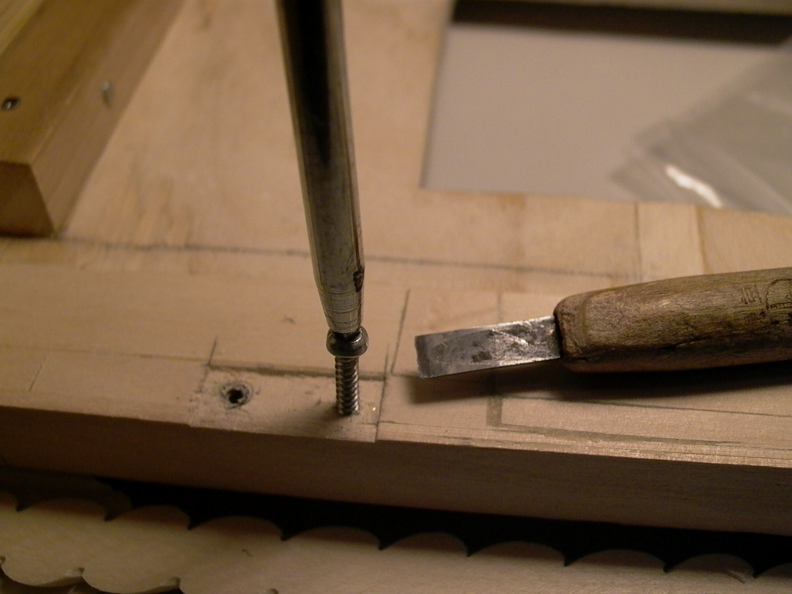
Next, hinges were added to the case for back and front doors. Position and hole were marked by tracing with a pencil. Then, a thumbtack was used to push a pit in the center of the where screw holes would be located. This will act as a starting guide hole. Instead of drilling, a wood screw was used to cut the thread into the wood (fig. 109).
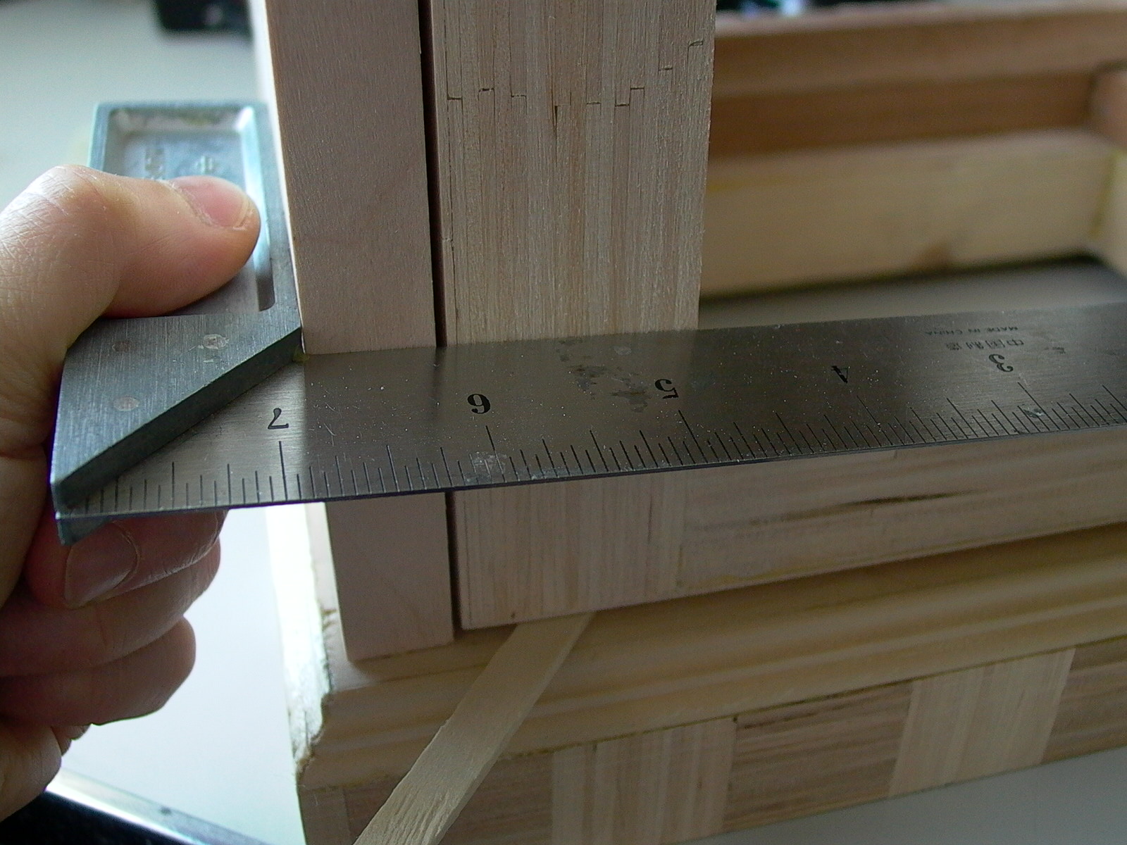
The edges of the doors (back and front) were then sanded for squareness and so that the gap around its perimeter is equal to the thickness of two tongue depressors. Tongue depressors were then used to veneer the edges of each door (there’s no veneer at where the hinges would be). Hinge holes were drilled and doors were mounted.
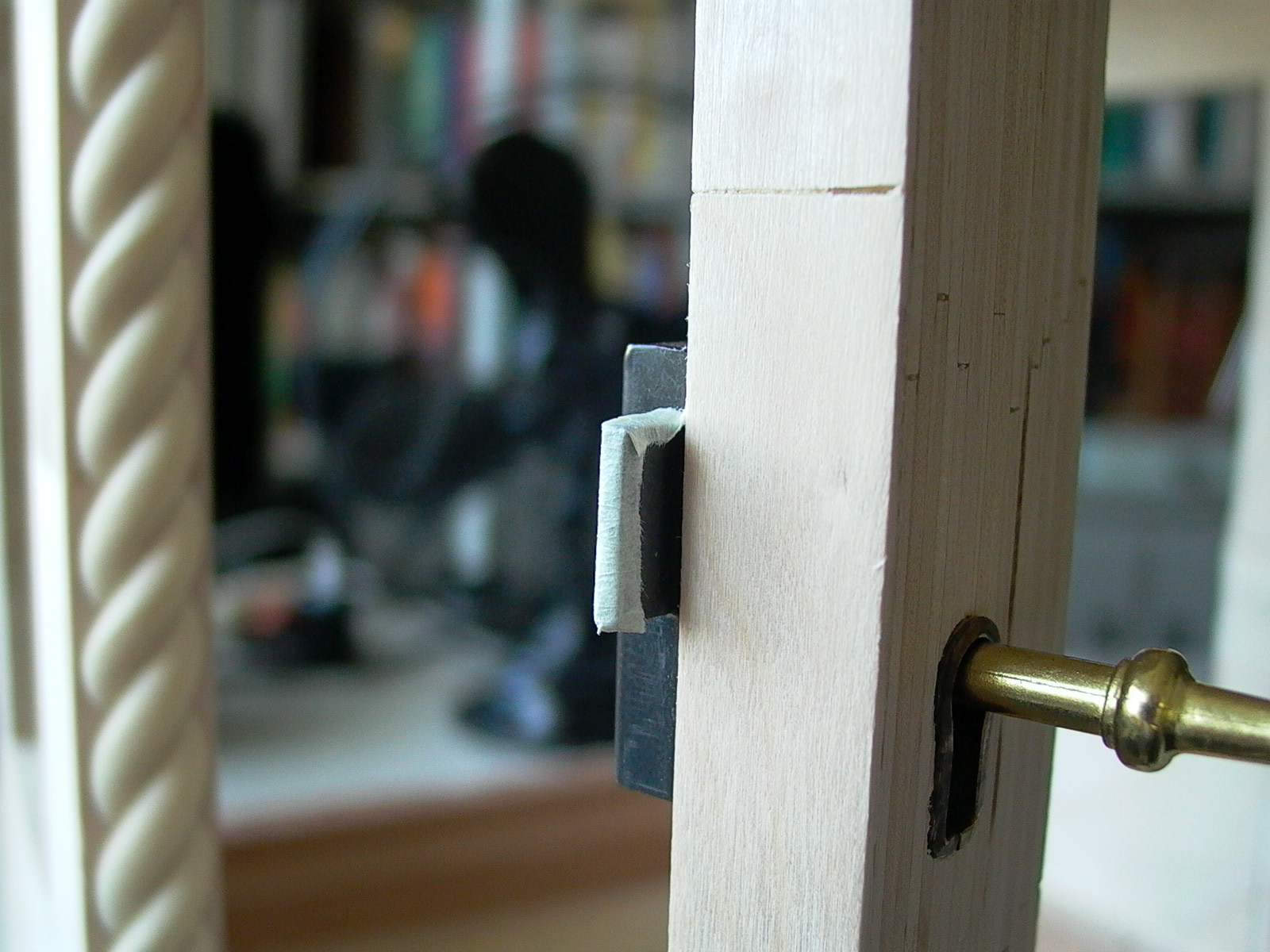
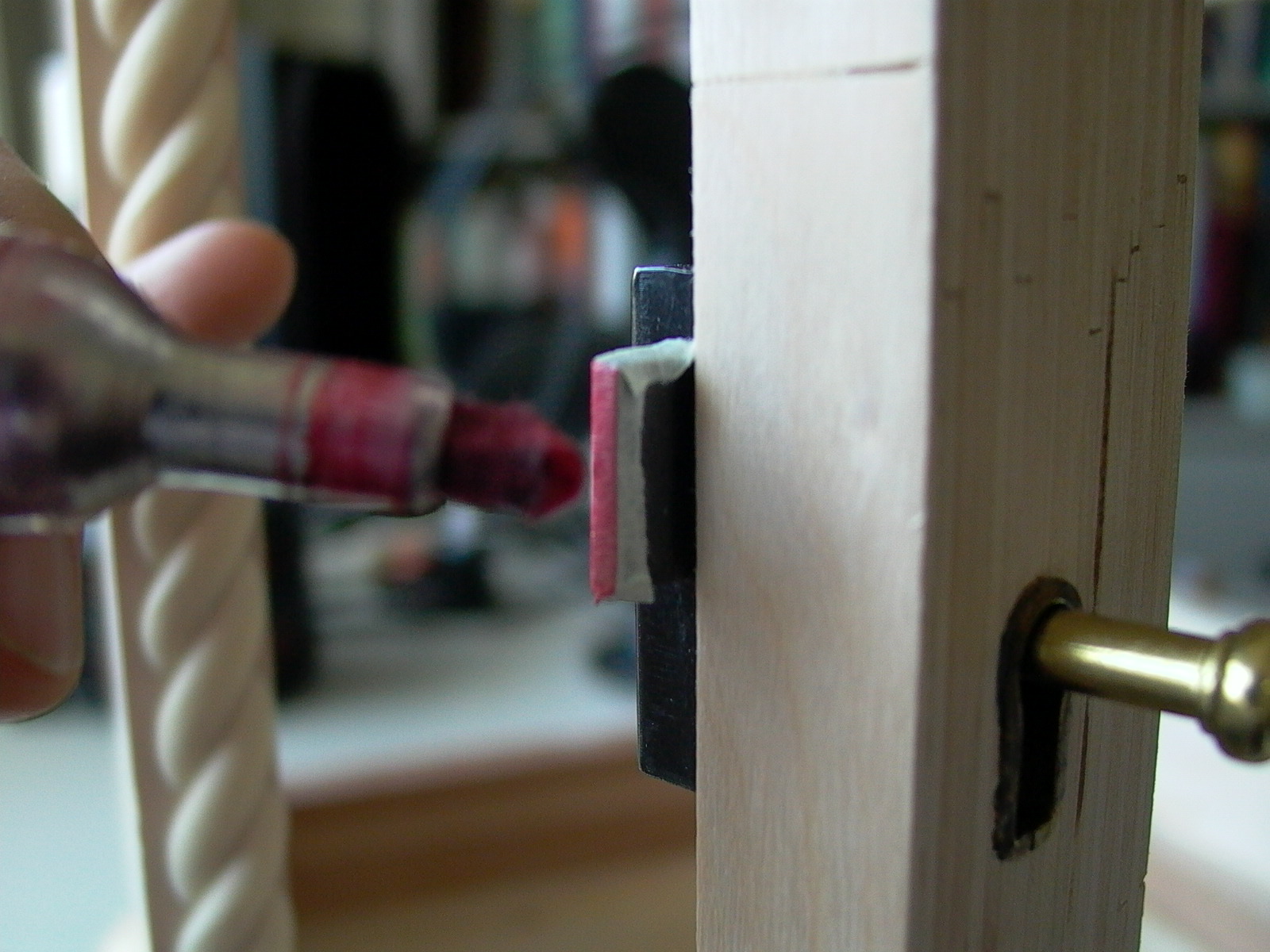
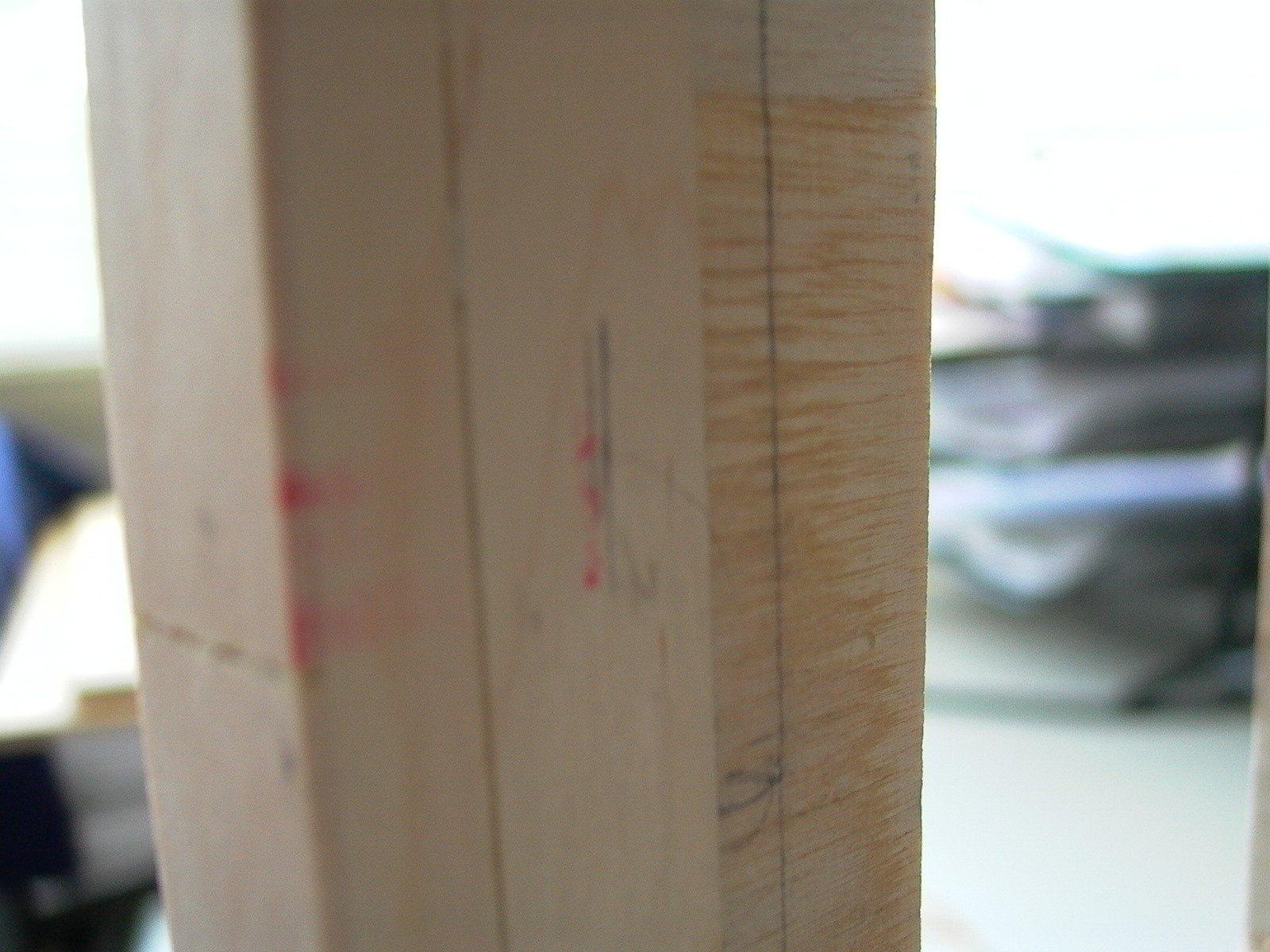
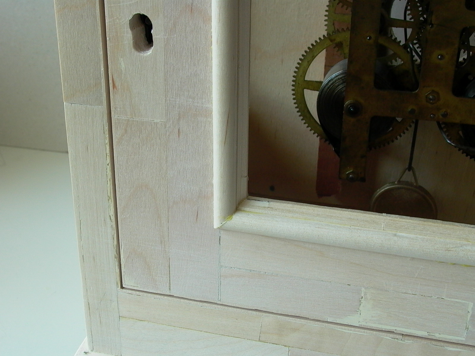
Locks were then installed on the doors. To mark the position of the bolt, a piece of masking tape was taped on the bolt (fig. 110), and covered with ink (fig. 111). Door was closed at where it should be (fig. 112) and the key was place in the lock and turned to extend the bolt, stamping a mark (fig. 113). The marked wood was then scooped out, forming a hole for the bolt of the lock. Notice the rope molding in the photo…in the end, I decided not to use it.
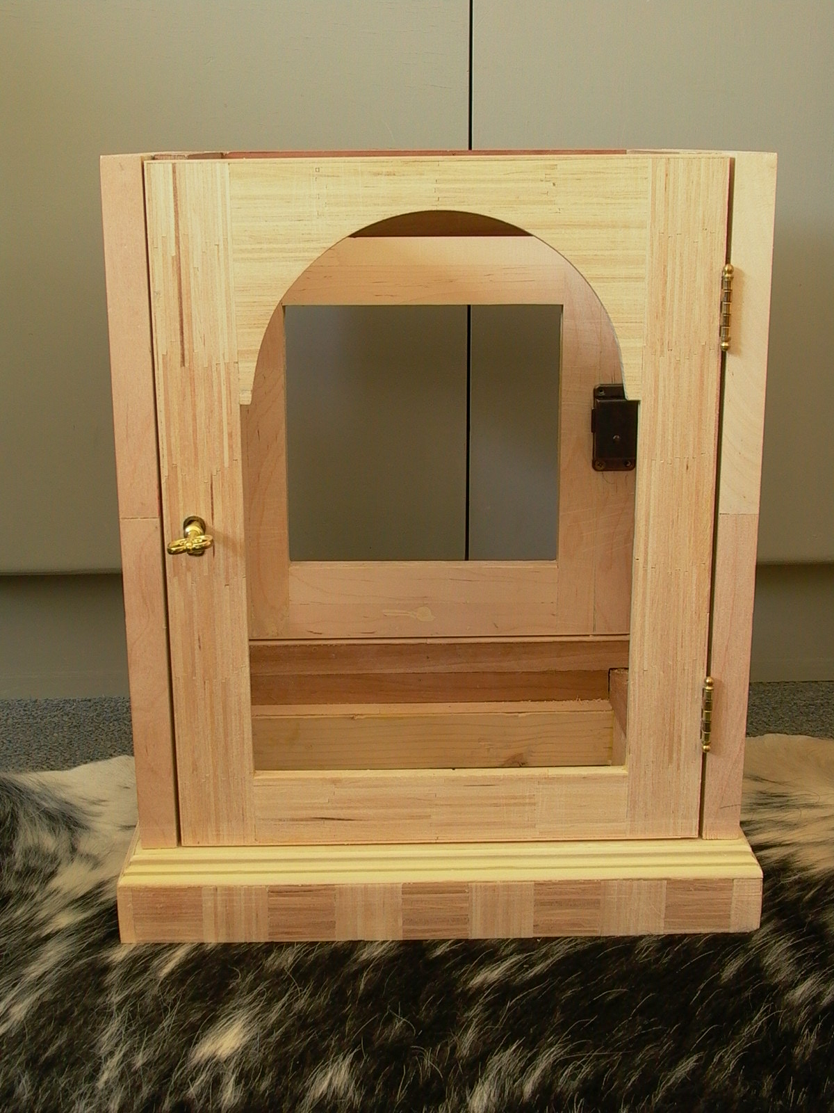
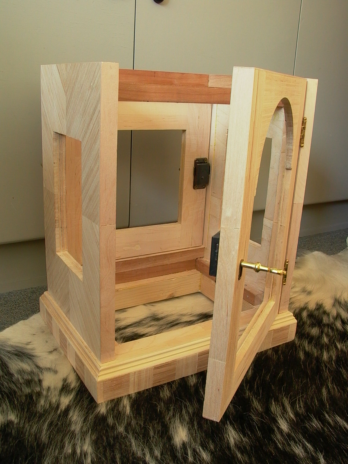
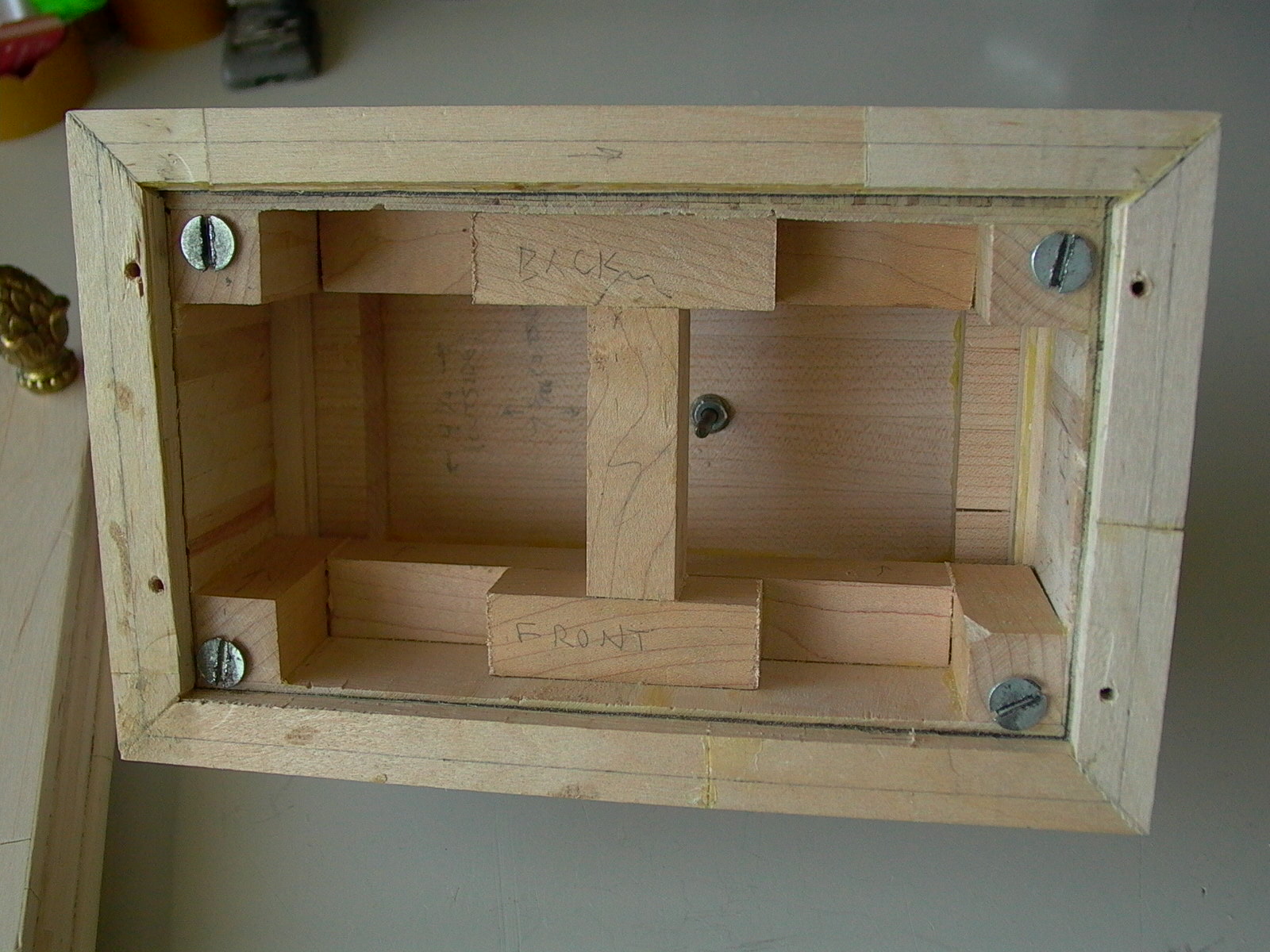
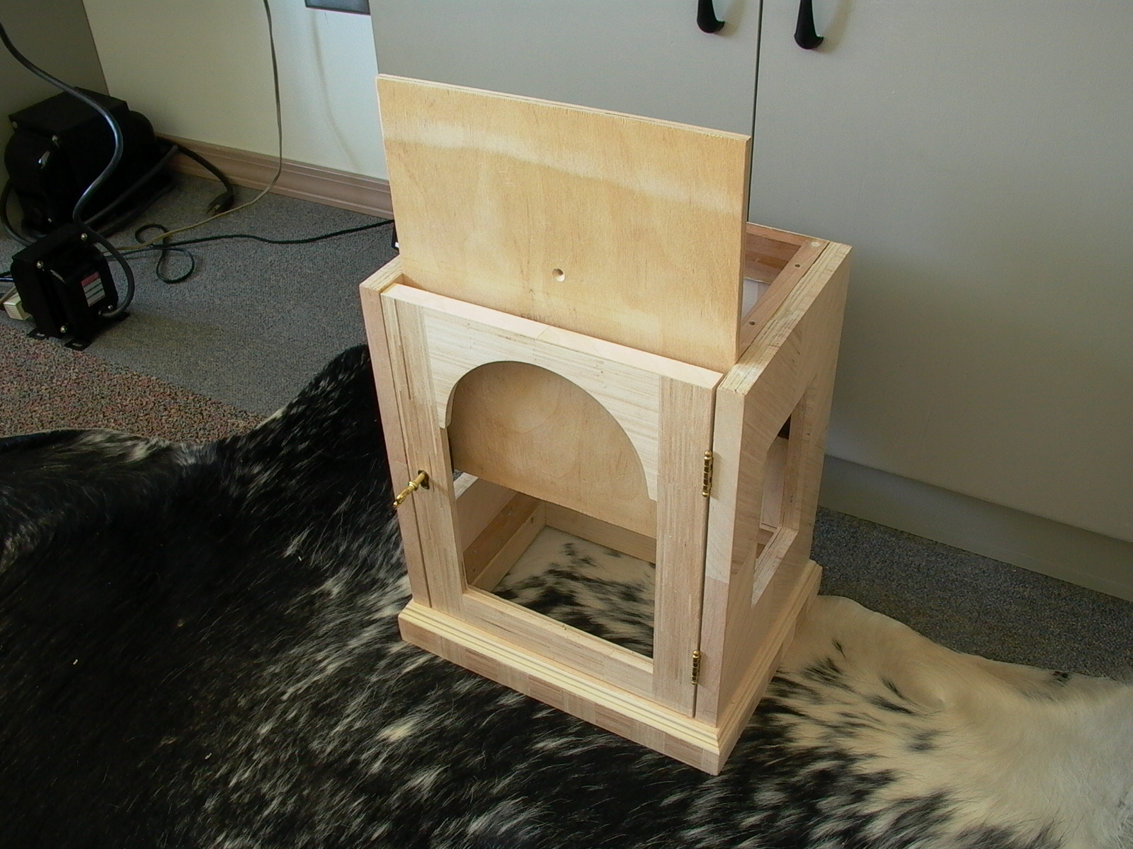
The front board was slid in (fig. 116), and held in place by four flathead screws into the front end of the corner support bars. Holes for the movement (hands shaft, key winding posts, mounting holes, etc.) were drilled into the front board, movement was installed, and the top was screwed back on (fig. 117).
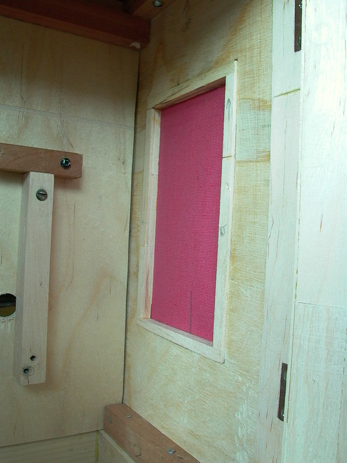
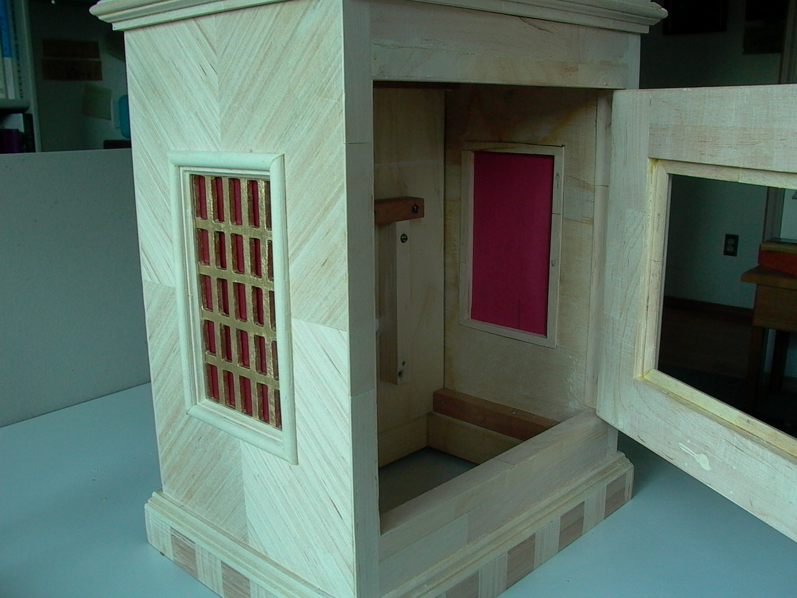
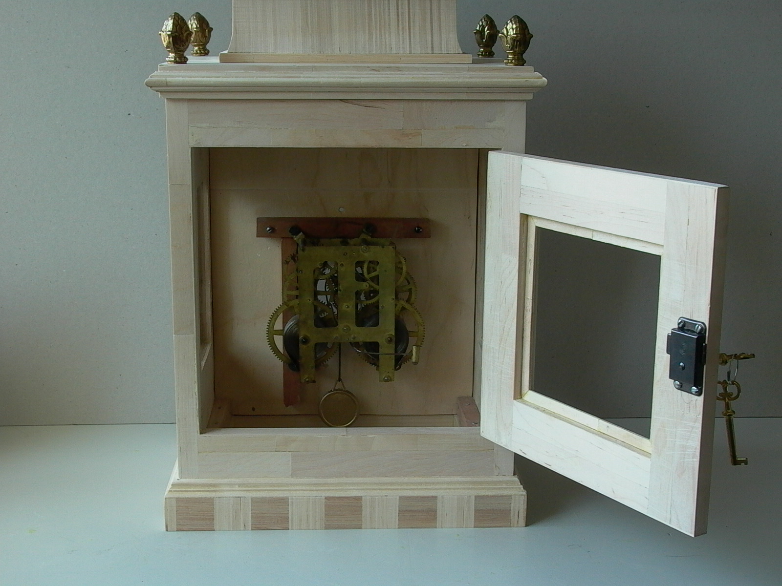
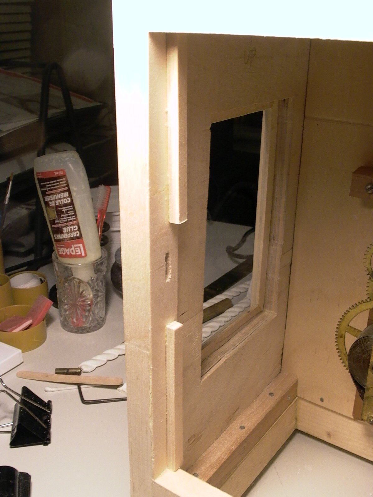
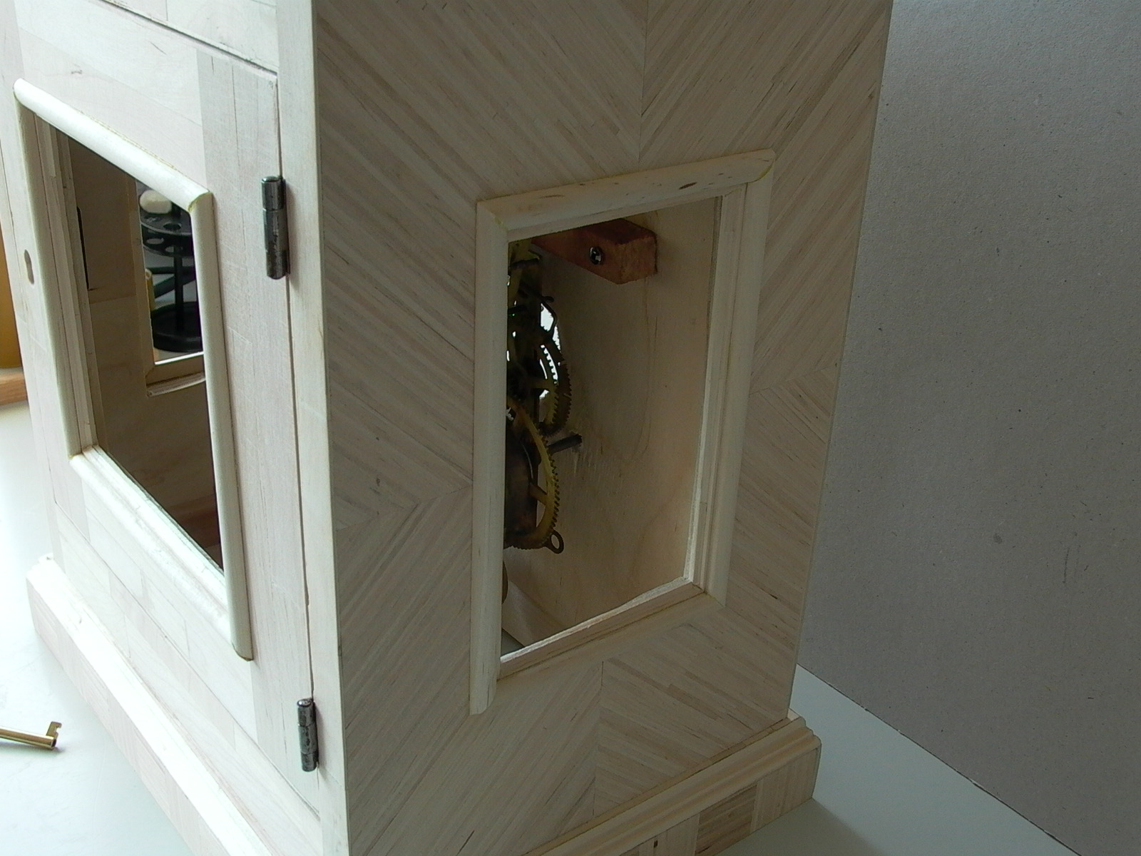
The back door and its lock were installed (fig. 118) and door stops were added (fig. 119) (“veneers” of thin craft sticks would later wrap around and run inside right up to the stop strips). Popsicle stick molding were also added around the cut-outs of the side boards and back door window (fig. 120 and 121). The moldings were also important in they form a ledge to hold glass or decorative gilles (see next section) in place.
Side Windows
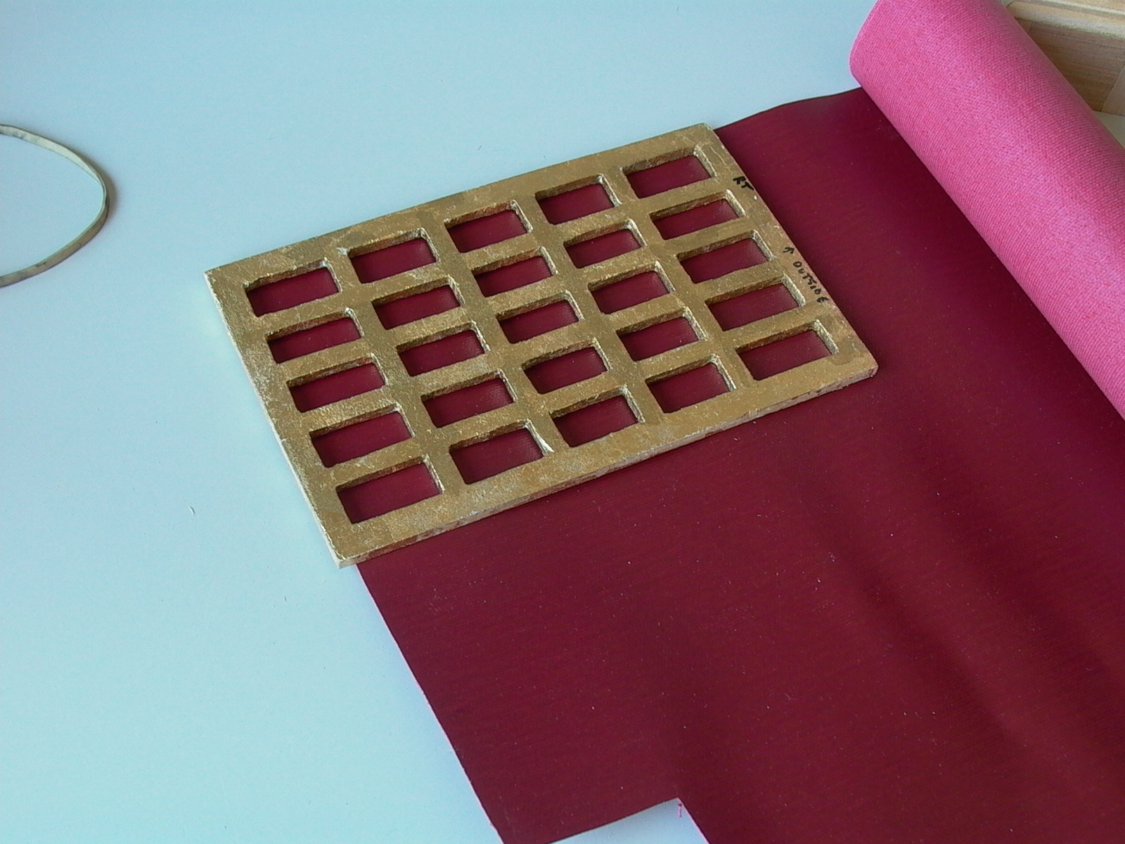
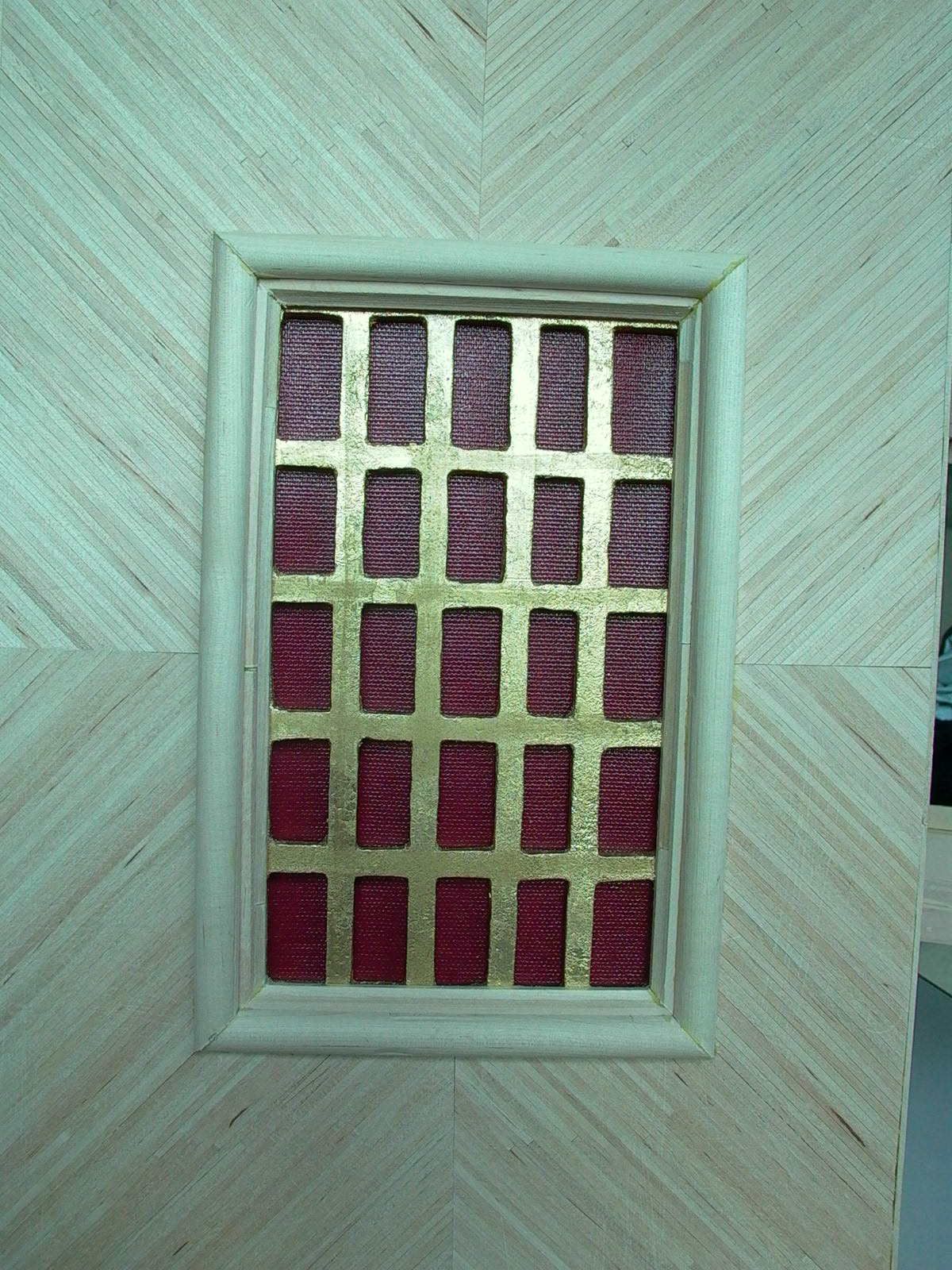
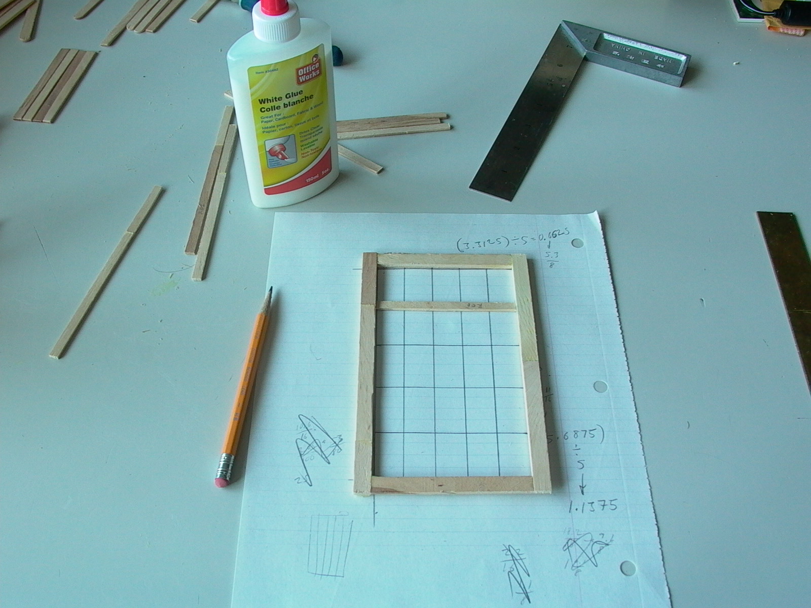
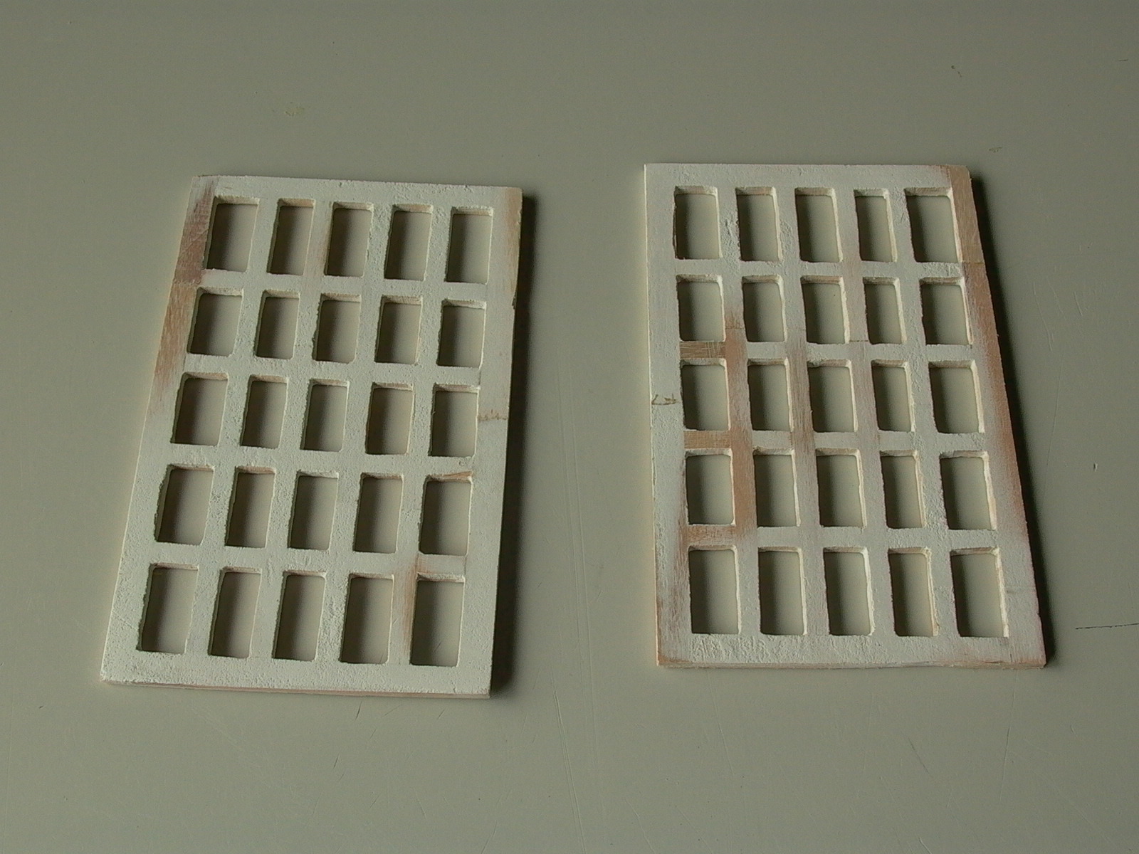
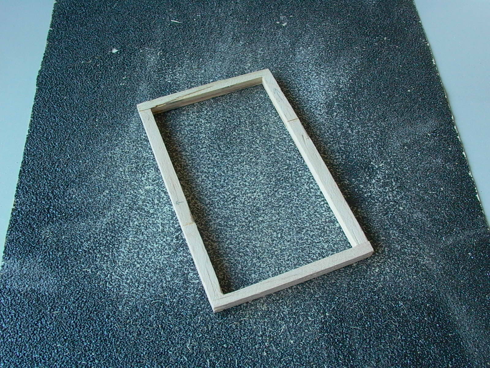
Two identical decorative grilles were then made for the side cut-outs. A simple yet classy grid pattern was used and could easily be made from Popsicle sticks that were made narrow by sanding. The grid was composed of two layers and stick were arranged so that joints do not overlap (for strength). First, a full sized drawing was made to act as a positioning guide (fig. 122). Then the outer frame was made (fig. 123).
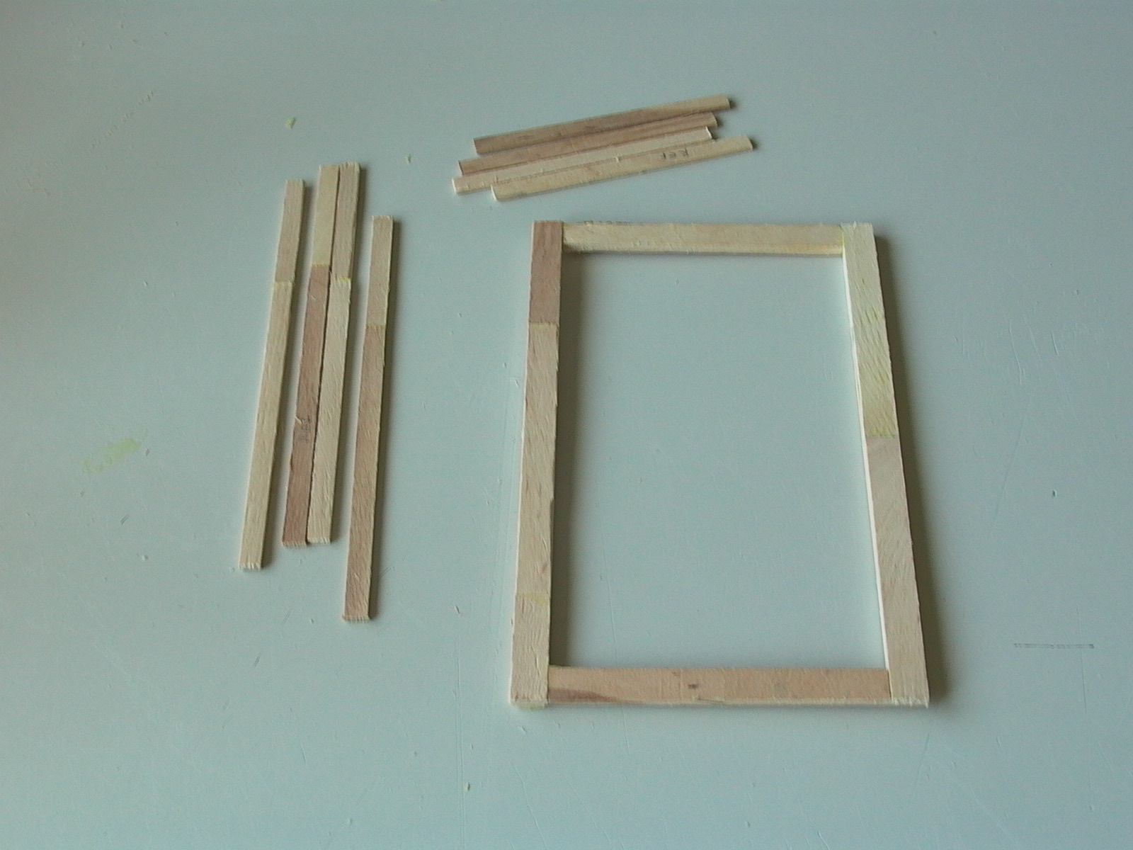
To make the grid, the outer frame was place on the guide sheet. Then for the first layer, full length horizontal strips, with glue on their ends were placed following the drawing. The glue was allowed to dry, then the vertical bars would be made from segments, also with glue on their ends, and fit into place between horizontal strips, after which glue was allowed to dry again.
To build the second layer, the process was repeated except that this time, vertical strips ran full length while the horizontal was broken into segments.
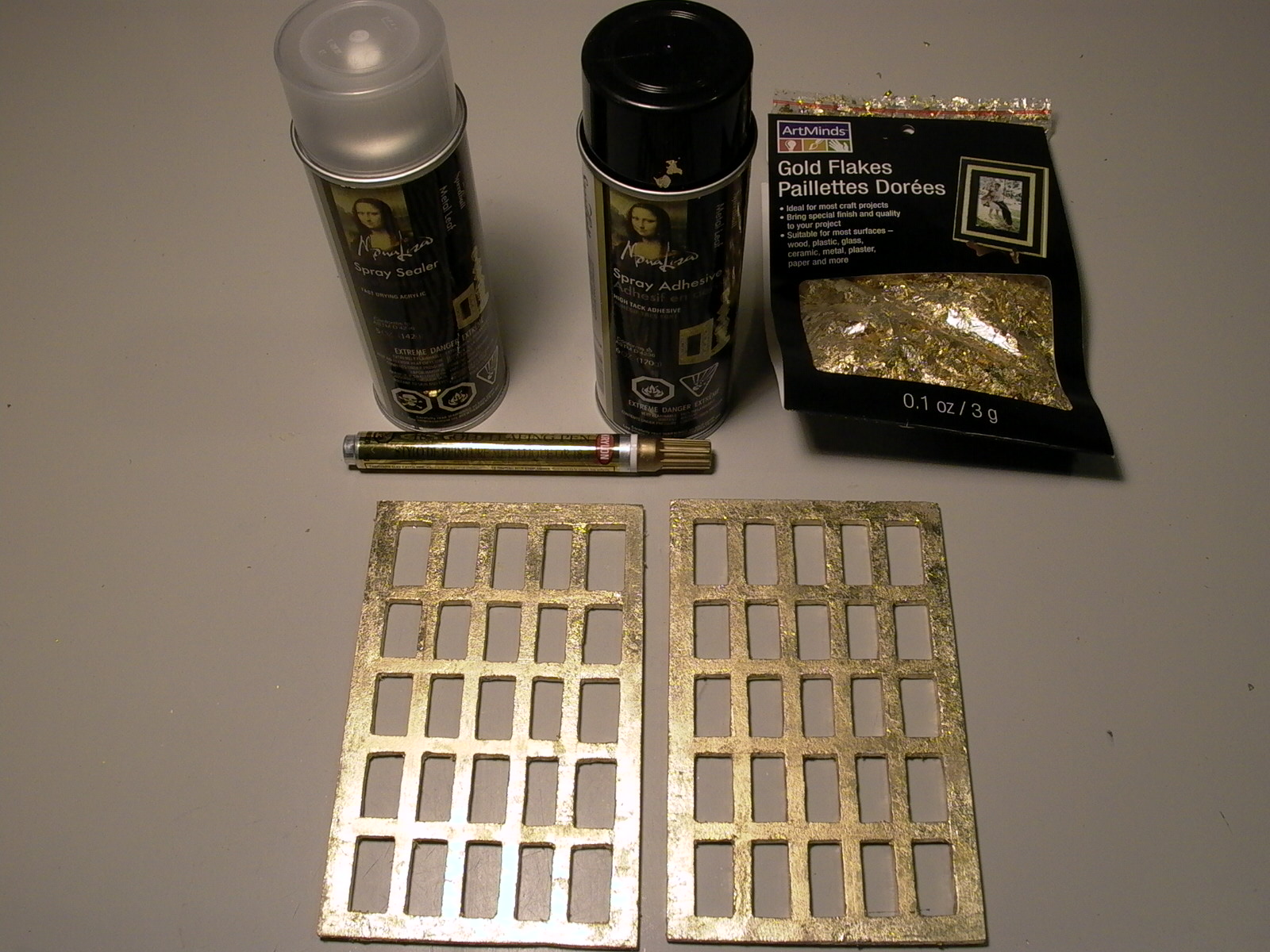
Both windows were then sanded and coated with homemade eggshell gesso (recipe coming soon) as a primer for gilding (fig. 124). A gilding kit, purchase from a craft store, was used following the instructions (fig. 125). If using metallic leaf, it is important to seal it with an acrylic spray as the metallic colors can be easily rubbed off. Only one side of each grille needs to be gilded but I did both (all four sides), allowing to extra sides for practice.
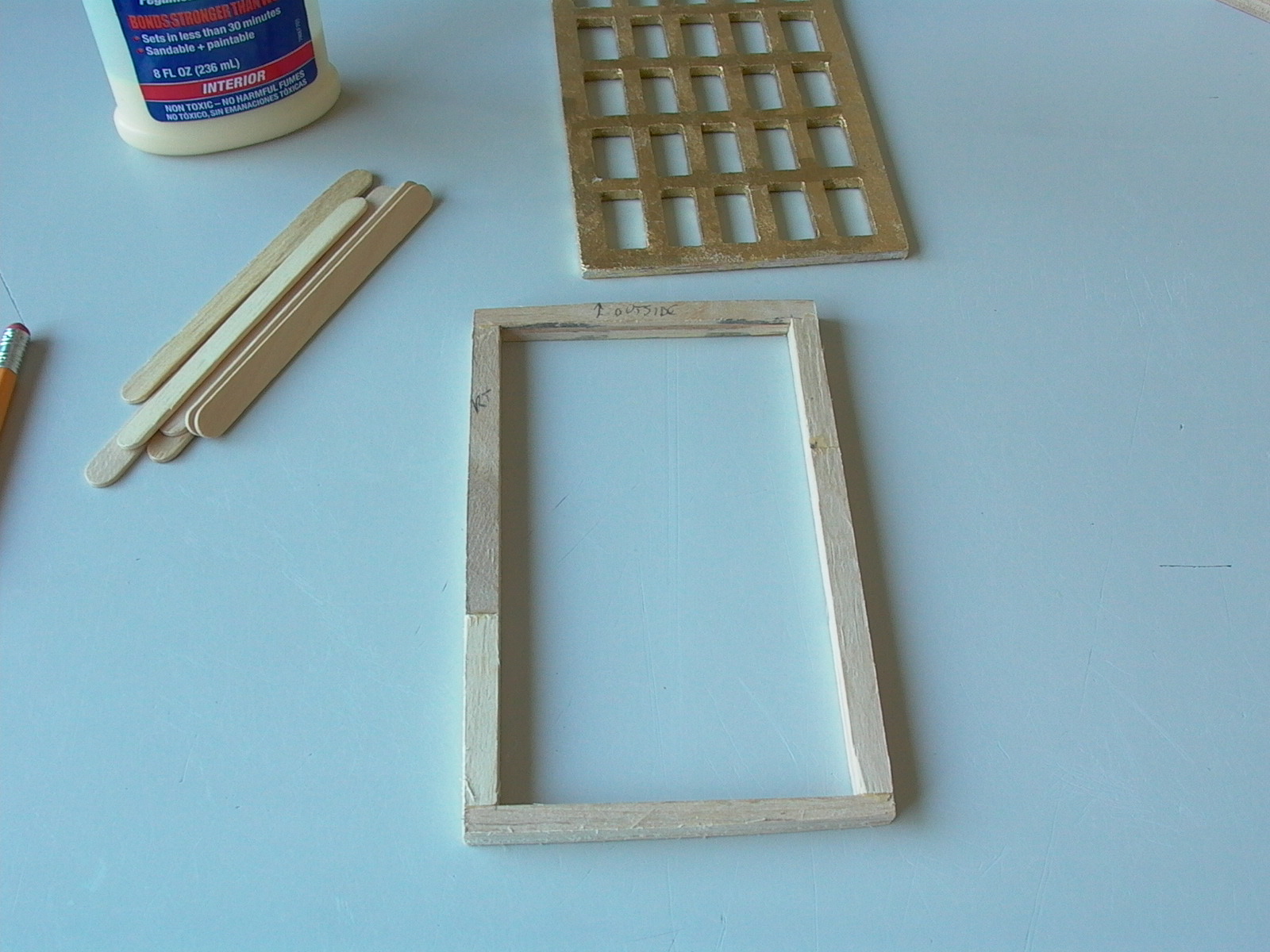
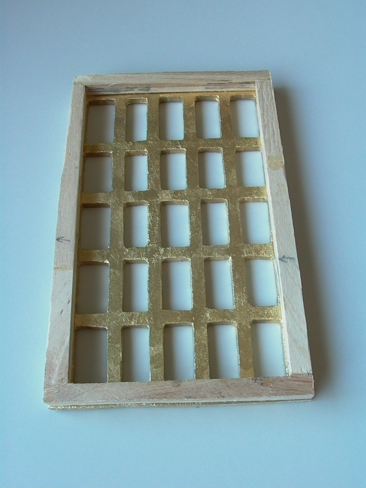
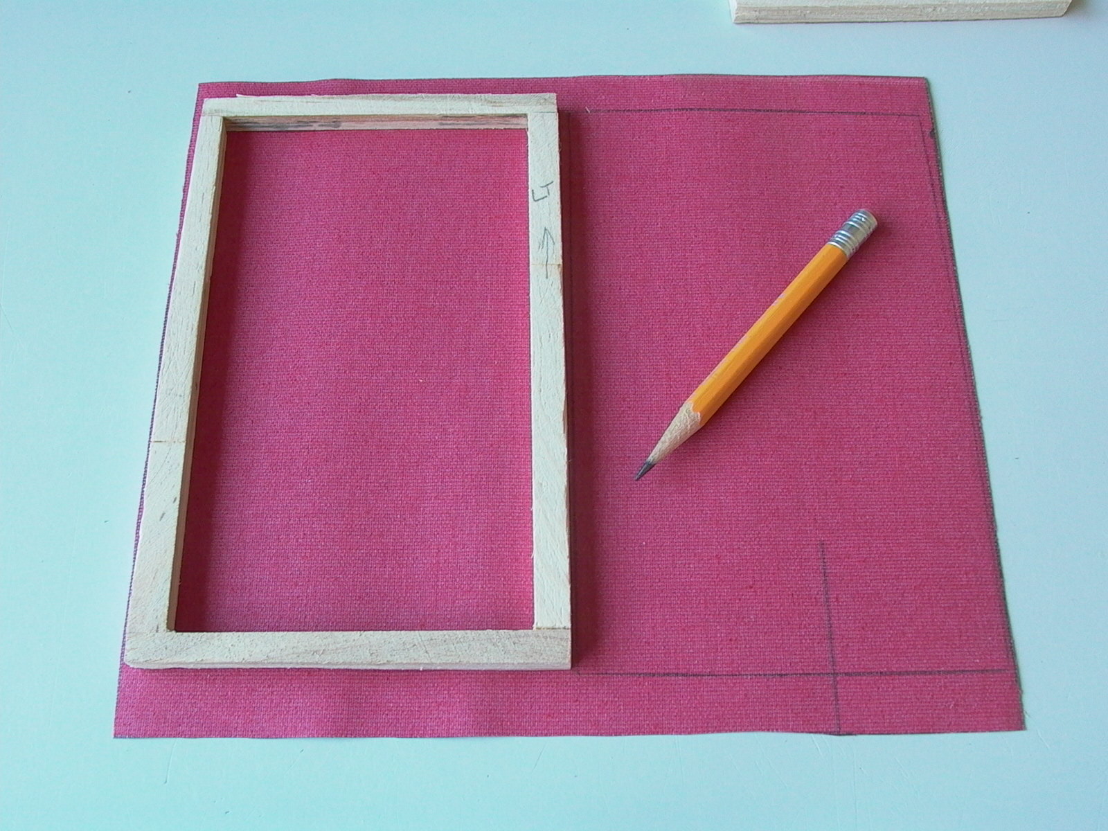
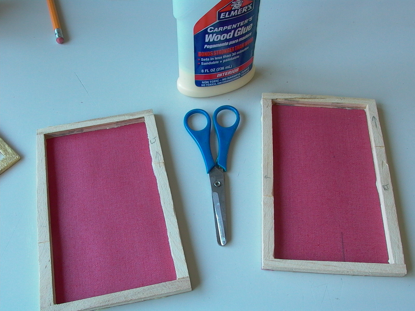
A stretcher same size as the outer frame of the grids was then made, also using Popsicle sticks. The thickness will depend on your side boards (do not glue to the grid) (fig. 126 and 127). Sides were sanded for snug fit into the cut outs (fig. 128).
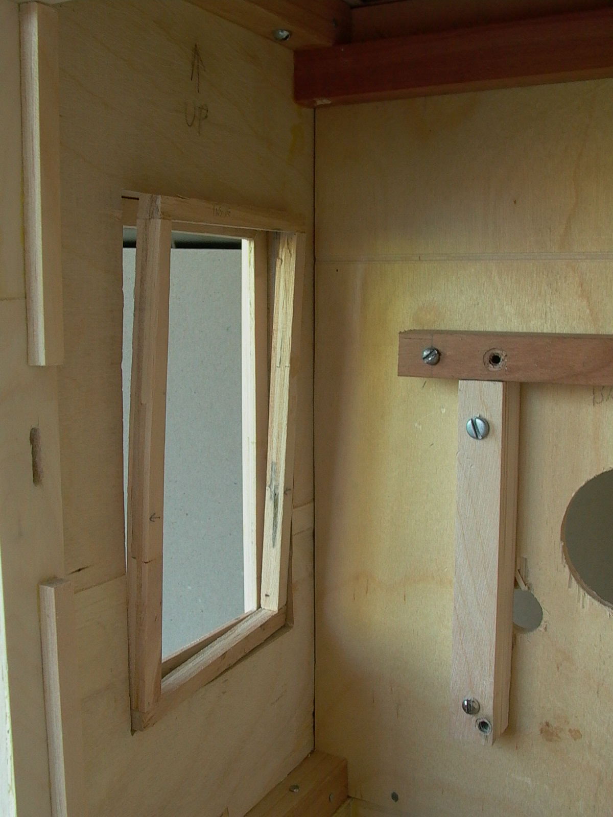
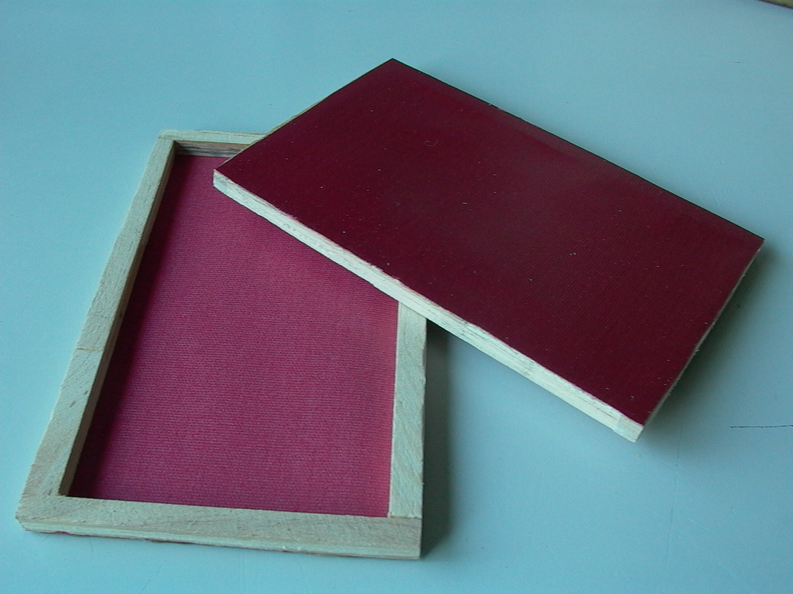
Pieces of buckram bookbinding cloth, trimmed to size of the grids (fig. 130) were glued onto the stretchers (fig. 131-133). Grids were then pushed into the cut outs with gilded side facing out. Next, stretchers were pushed into place (fig. 134) so the grills touch the cloth side (fig. 135 & 136). Do NOT glue stretcher and grid into cutout as the whole case will be take apart later for finishing (staining and varnishing).