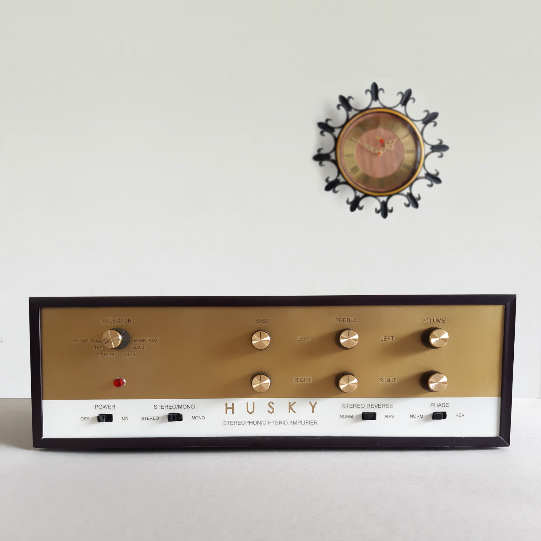
Build a tube amp in the style of a Mid-Century Modern (MCM) hi-fi stereo set and enjoy the classic warm sound of vacuum tubes!
Introduction
After the success of my previous project – an old English style multi-band crystal radio using the Australian “mystery design” – it was time to fast forward to the late 1950’s. The 50’s was exciting and optimistic time for many Americans: people were able to enjoy leisurely activities, public space travel seem like it was just around the corner, and television and high-fidelity stereos systems were becoming common in middle class American homes.
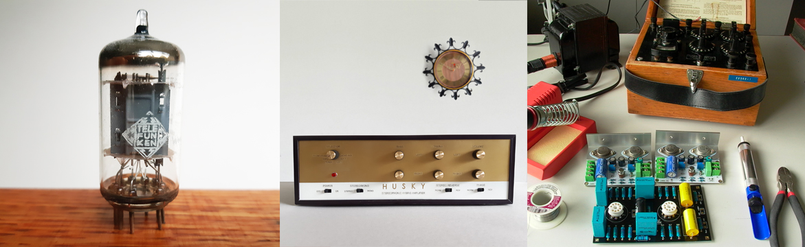
When the iconic ’57 Chevy Bel Air starting roaming the streets at the dawn of the space age, Elvis Presley ruled the airwaves, and high-fidelity audio reached its golden age. Although the majority of electronics made around this time built with vacuum tubes, manufacturers of electronic goods produced their best ever quality household hi-fi stereo sets around this time with continuous production into the 60’s with very little changes until the transistor started taking over. Today, vacuum tube-type stereos of the 50’s and 60’s (or “valve amps” if you are from the UK) are highly sought after by both audiophiles and mid-century modern collectors/enthusiasts alike.
By the 1970’s, the vacuum tube fell out of favor while the majority of consumer electronics were now built with transistors and integrated circuits. Televisions and stereos from Japan started to invade North American homes while several US manufacturers started outsourcing production to Japan and later Hong Kong.
The 1980’s saw the ugliest things ever produced, from furniture to cars to houses/buildings and things in between including consumer electronics. In the world of electronics, it was the dawn of the throw-away era which persists to this day, when gadgets were meant to be replaced rather than repaired. Companies that once took pride in the quality of their products began mass-producing junk because it was profitable, especially if manufacturing was outsourced.
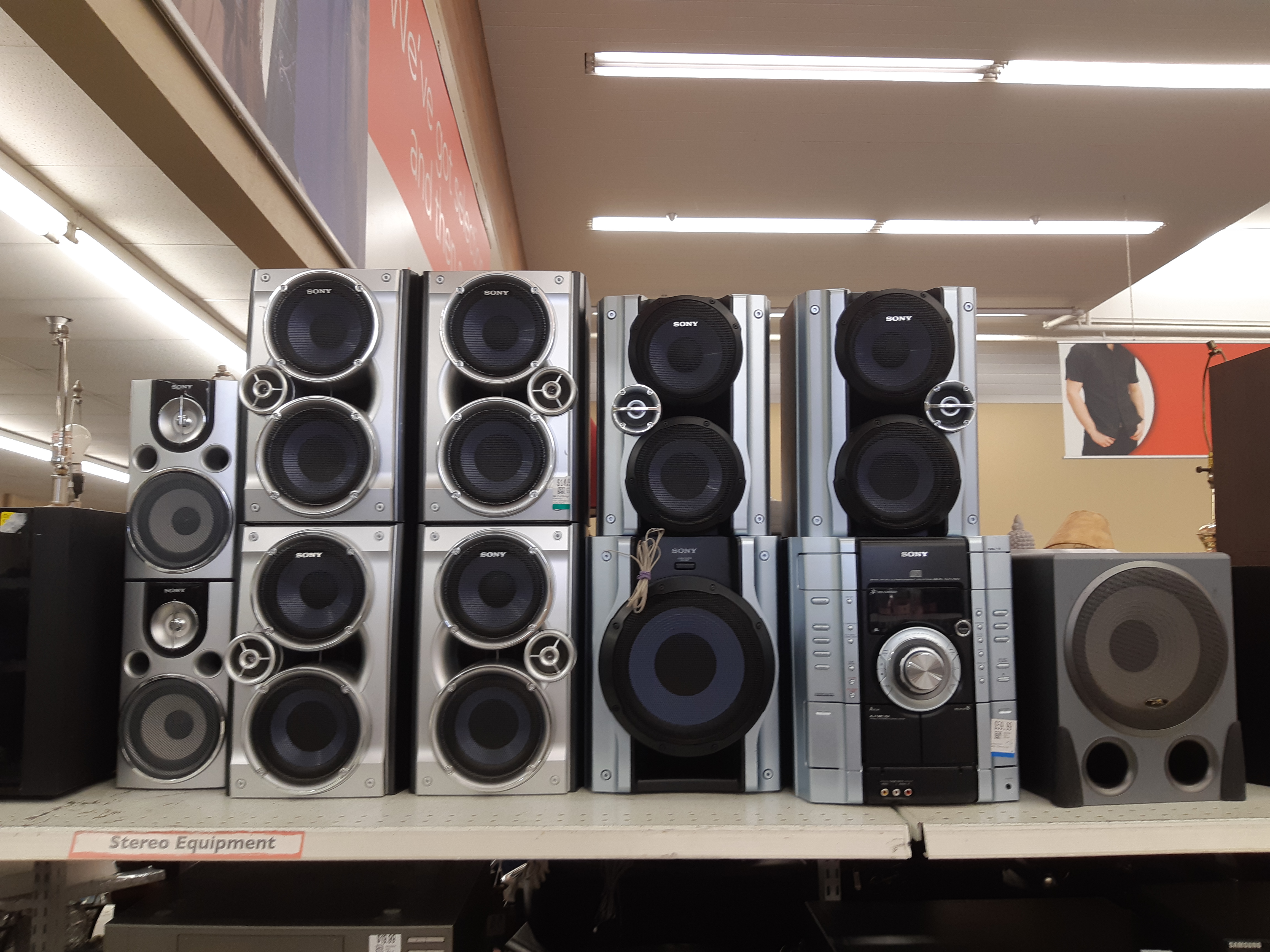
When the 1990’s rolled-in, the quality of mass produced goods has hit rock bottom and the market was flooded with junk. Most household electronic goods of this decade are easily recognized by their black colored shells with black plastic face plates (members of Facebook groups about vintage hi-fi stereos refer to 1990’s stereo components as “Black Plastic Crap” or “BPC” for short, although the term may also encompass poor quality plastic sets from the 80’s to present regardless of color).
Fast forward to 2018: a seemingly never-ending supply of junk products from the 1990’s now fill the shelves of Value Village (a.k.a. Savers) and other thrift stores worldwide. The shelves of secondhand electronics are packed with “Black Plastic Crap” stereos while the chances of finding a vintage tube-type hi-fi set are slim-to-none.
One day at a Value Village while searching the electronics section for vintage tube gear (of which I found none), it sudden dawned on me that most 90’s BPC stereos have reasonably well built outer shells that can be repurposed in many DIY electronics projects. A BPC amp (for example, a Pioneer stereo amp/receiver built in 1994) with a strong shell will set you back about $15-30 (even cheaper at charity stores or practically free if you have the patience to ask around) while a blank project enclosure box of the same size from an electronic components supply house can run anywhere from $150-300 – a difference of a whole order of magnitude in price! Then, I wondered: “Can I turn an ugly 90’s BPC stereo set into a 60’s style tube amp?” Well, let’s find out…
But first, a word of warning…
DANGER: High Voltage!!!
This project involves working with high voltages of up to 300 volts – more than enough to cause serious injury or death. DO NOT attempt to work with tube equipment in any way, shape, or form if you are unable to unequivocally point out the danger spots inside unless you can find someone qualified to assist you. Or better yet, take the amp to a qualified technician and let them do the work. If you choose to work with ANY type of tube equipment unassisted or unsupervised, do so at your own risk and responsibility. As with all projects, any information from this website upon which you take action is entirely at your own risk and responsibility.
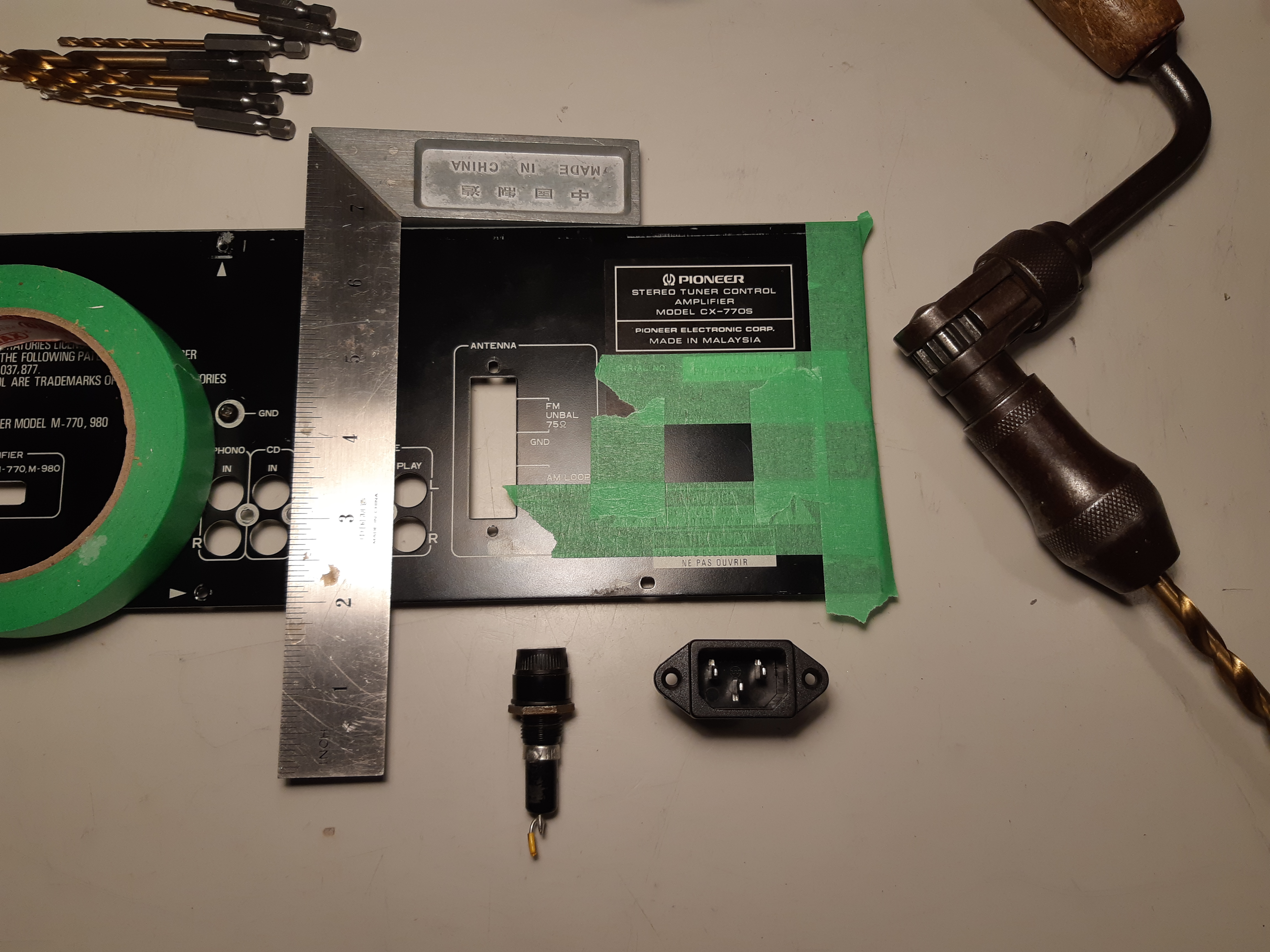
Choosing a Junk Set to Repurpose
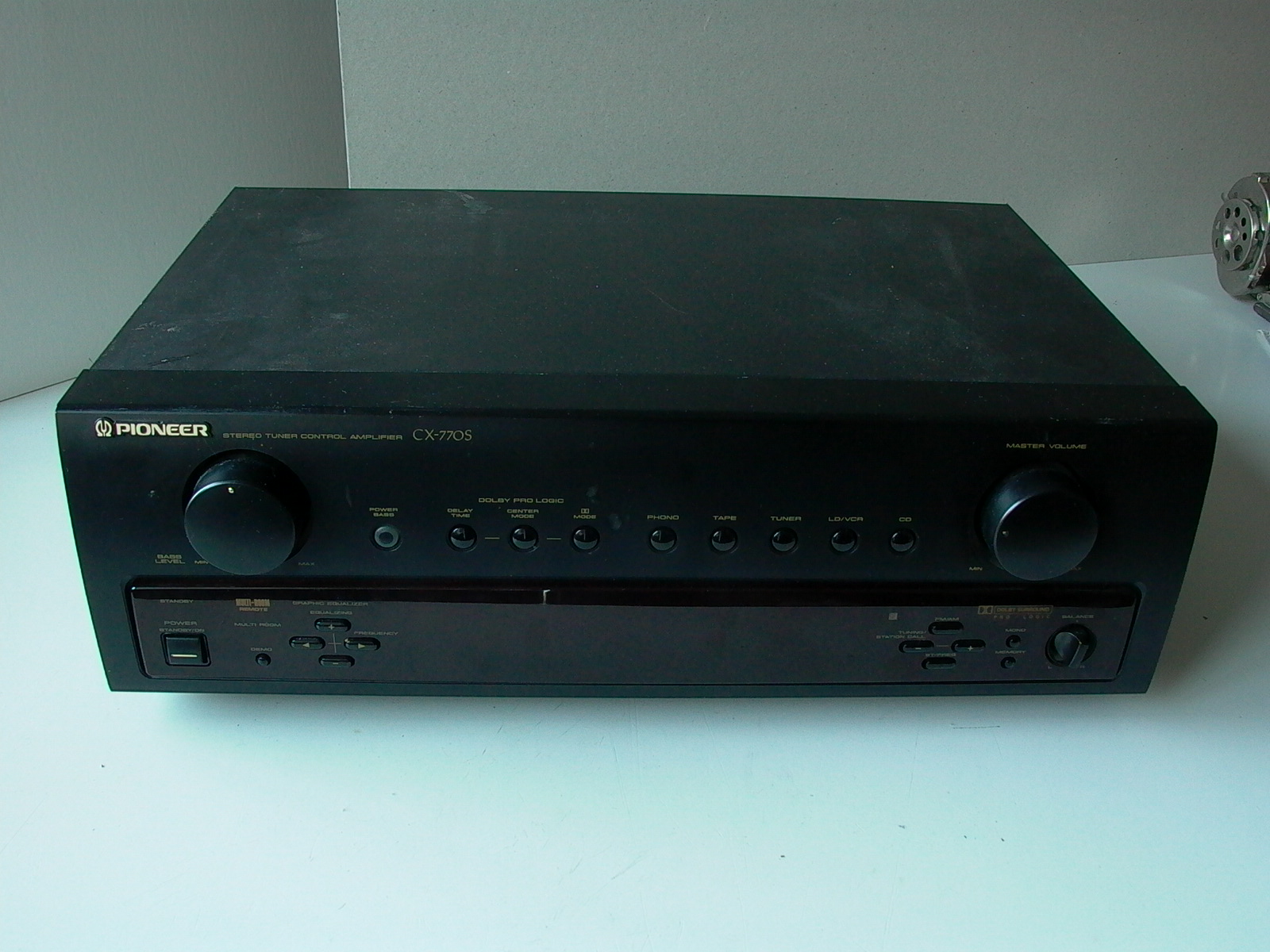
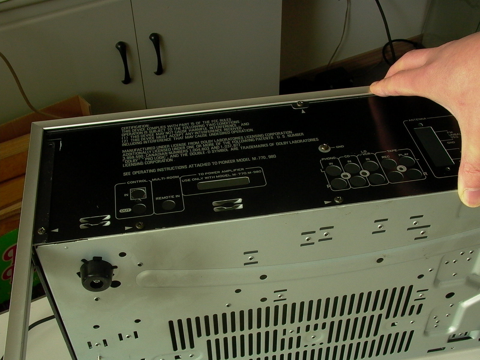
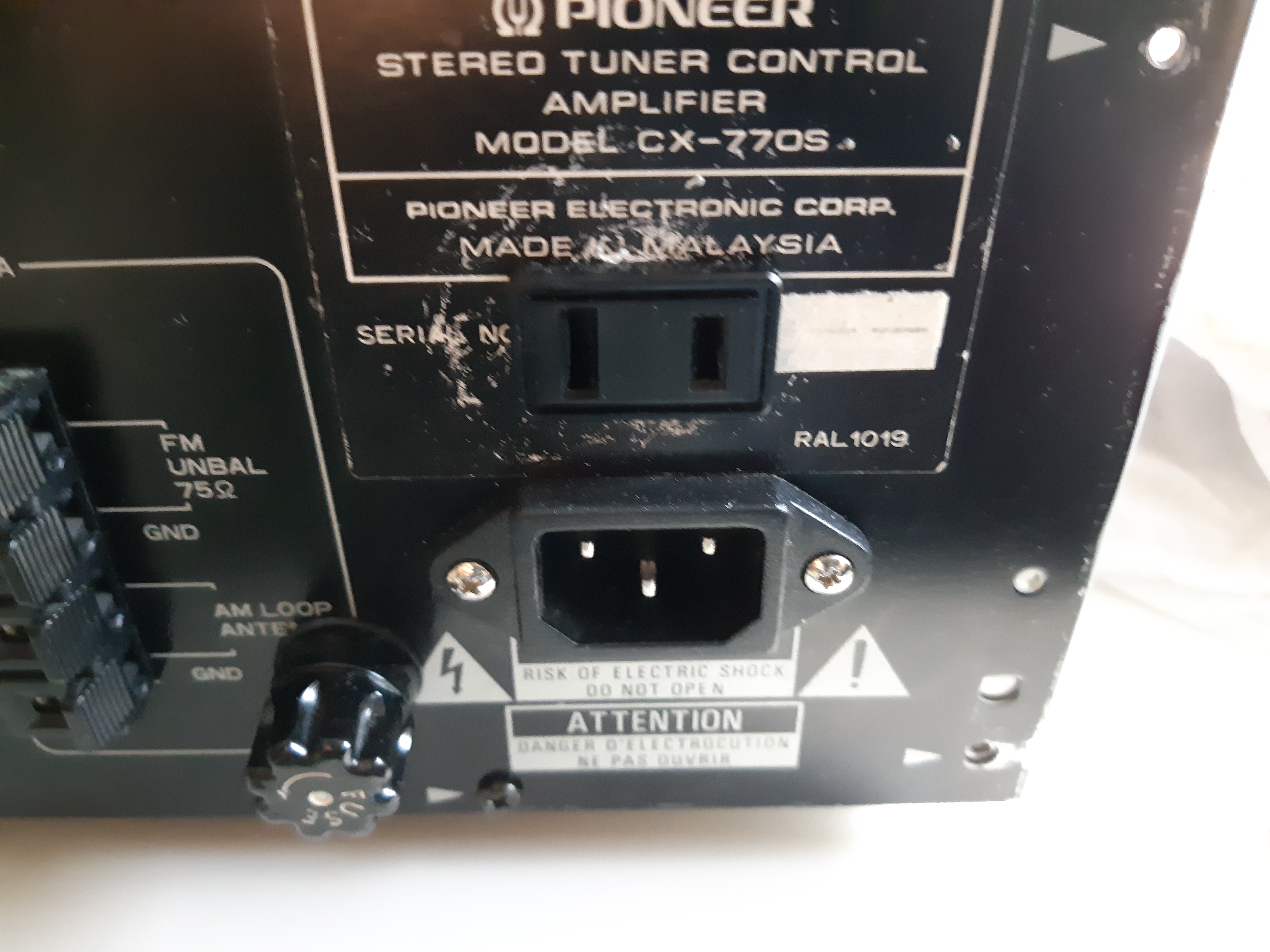
While at the Value Village thrift store, I picked up and purchased a Pioneer CX-770s that will be my starting point for this project. Introduced in 1994, the both the Pioneer CX-770s and CX-770 are not really sound systems per se, but rather control boxes for the Pioneer 770-line of stereo systems. As I held the set in my hands, a brief flashback to my childhood occurred as silly songs of the period like “Whoomp! (There It Is)“, “Sweat (A La La La La Long)“, “Mr Wendal“and “If I Had No Loot” started to play in my head (by the time the Spice Girls appeared on the music scene, I have already started collecting vintage tube amps…long before MCM was trendy); however, I had to keep in mind that while stereo systems with controllers were common in the 90’s, these systems were among worst ever sounding audio equipment sold on the market. At $14.99, it was rather expensive for such junk quality 90’s products but with access to an invitation-only sales night event, the price came down to around $10 (in my opinion, it’s worth no more than $5). When selecting a BPC stereo unit to repurpose, it is important choose a system that not only has a case with enough space to accommodate the components into which you will be installing but also with adequate ventilation (unfortunately, I had overlooked the latter); this is especially important if you plan to use output power tubes.
The Design
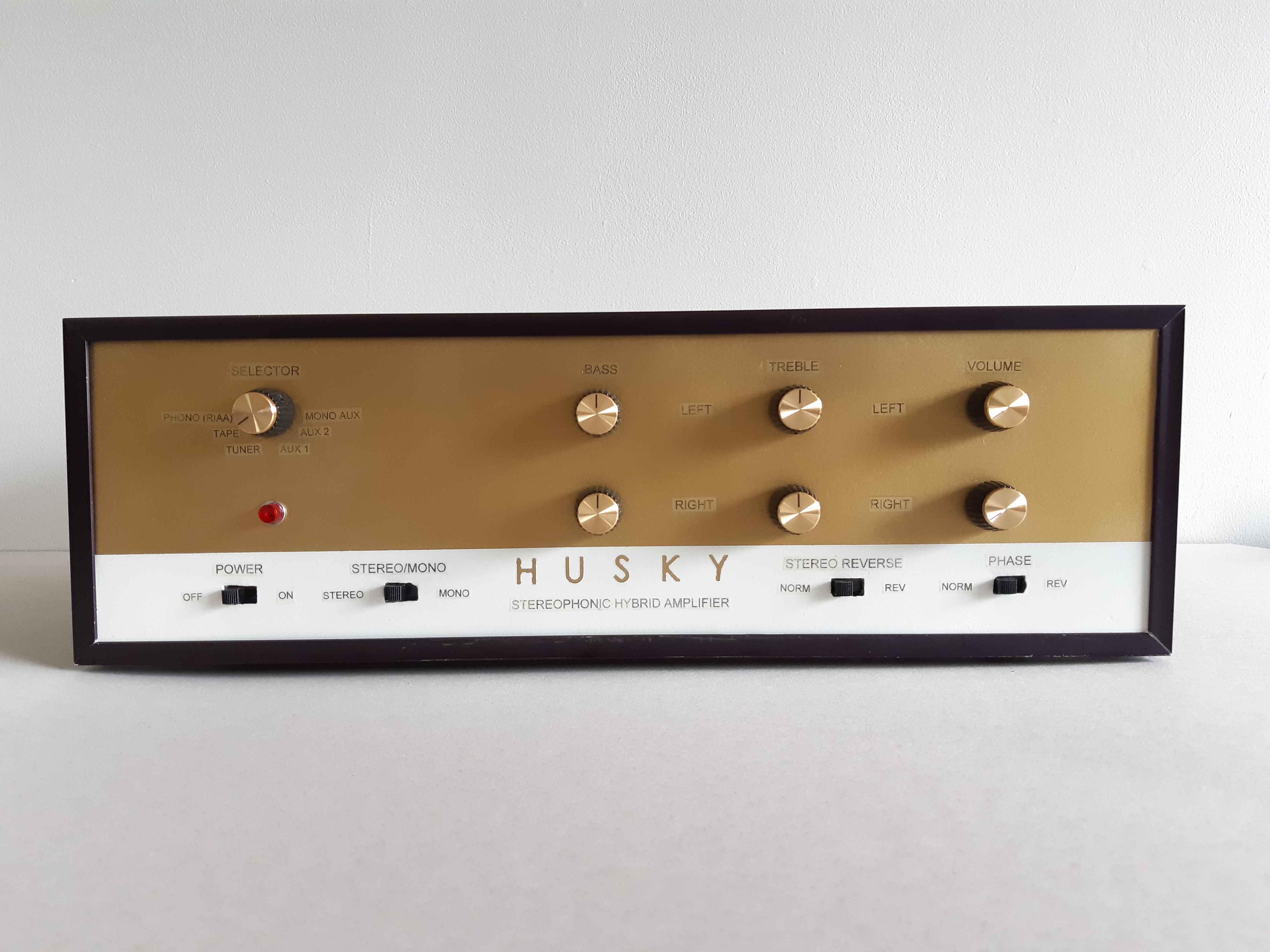
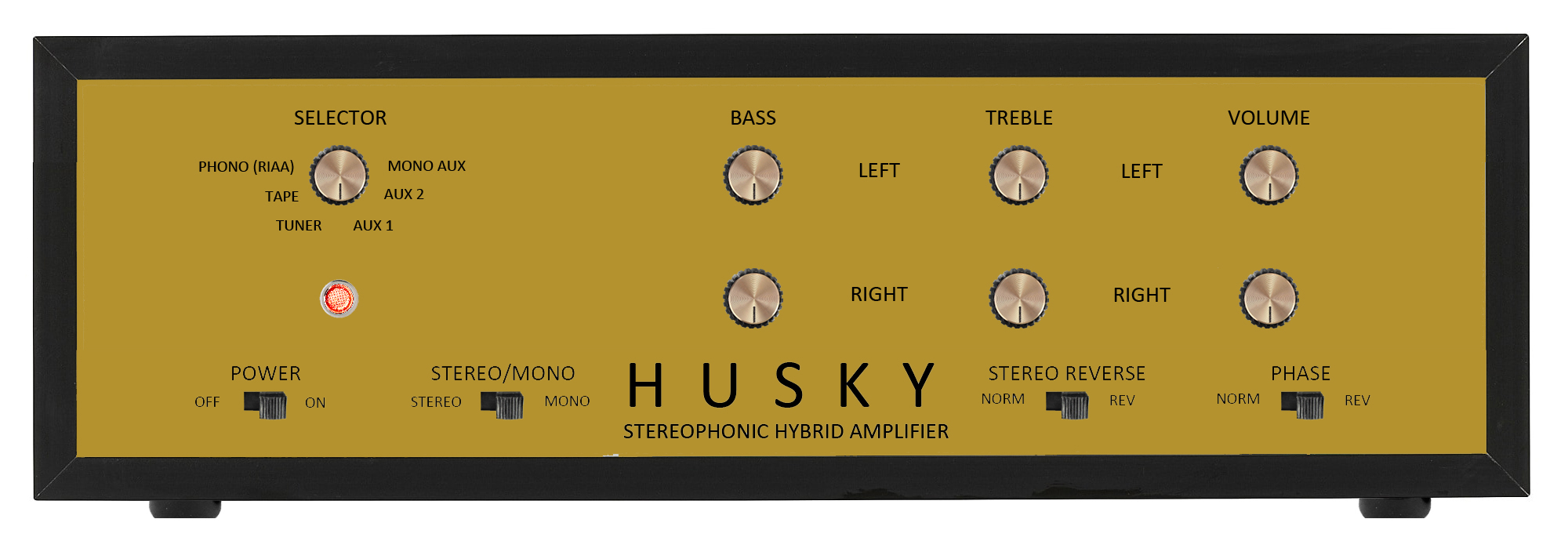
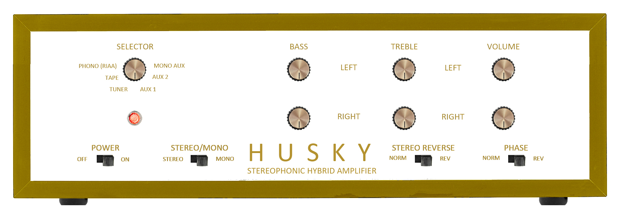
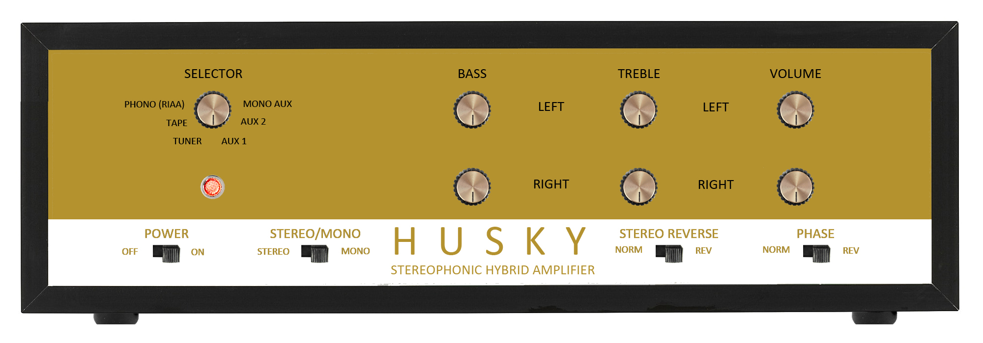
As soon as I acquired the junk stereo, the first step was to come up with a design for the exterior of the unit. In Photoshop, I created a mock-up of three possible designs in the mid-century style. As with the crystal set, I have decided to stick with the name “Husky Electric”, albeit with a more modernized font consistent with 50’s/60’s styling. While several members in a Facebook group about vintage audio preferred the gold faceplate, I have decided to go with the two-tone design.
For the actual working electronic circuits, the set will be designed as an integrated amplifier consisting of a power supply, line preamp, phono preamp, and power amp, all contained within the unit. Each individual section will be a separate circuit board module. With the exception of the power supply, each module will be assembled from purchased kits rather than built from scratch. Modules are inexpensive; a brand new and complete tube preamp kit (minus the tubes) that is based on a classic design, for example, can be had from $10 and up from Chinese sellers on eBay. In addition to low cost, a modular system is easy to assemble and wire into a single unit, allows for easy repair/troubleshooting, and makes future modifications possible while at the same time, give outstanding performance.
Rather than a completely tubed stereo set, I have opted for a transistor-tube hybrid design as it is much more practical. Hybrid designs using a combination of both vacuum tubes and transistors were common in household hi-fi stereo equipment in the mid to late 60’s during the transitional period between the two technologies. A properly designed hybrid amp offers the best of both technologies, allowing users to enjoy the advantages of transistors while experiencing the classic warm sound of vacuum tubes; thus, many high-end audio manufacturers today continue to use tubes in one way or another in their premium products aimed at serious audiophiles despite modern advances and innovations in circuit and semiconductor technology.
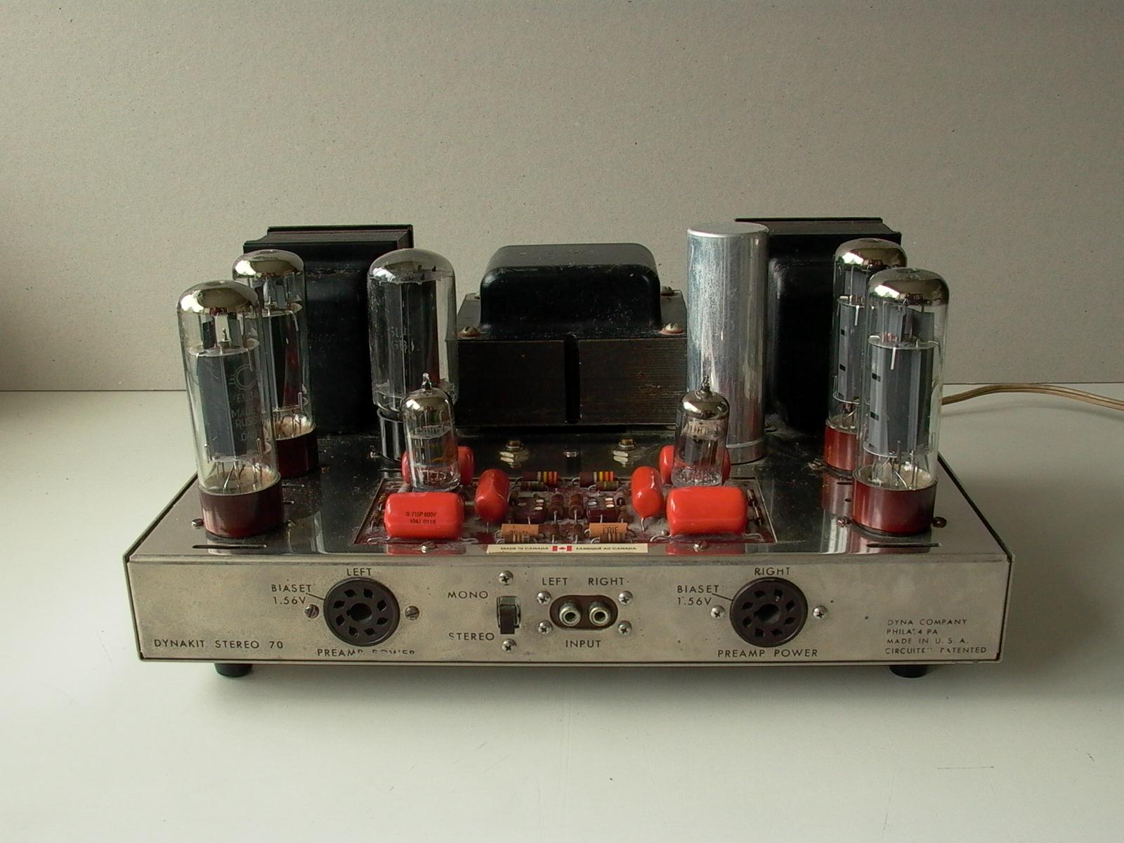
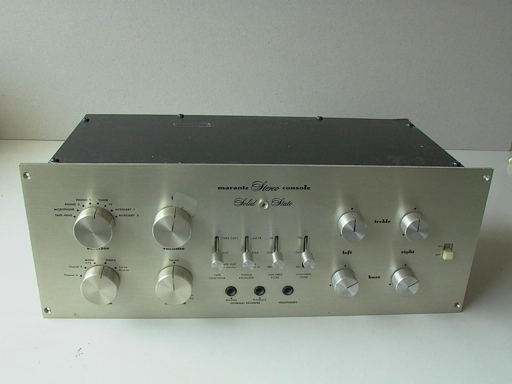
There are two ways to go about designing a hybrid system: a solid state (transistors and/or integrated circuit chips) preamp with a tube amp, or a tube preamp with a solid state amp. From my experience, my current stereo set up using a Marantz 7T transistor preamp to drive a Dynaco Stereo 70 tube amp sounded more like a solid state system than a tube system, and after a bit of research, other vintage and high end audio buffs have reported the same thing. On the other hand, those using a tube preamp to drive a solid state power amp have reported warm tube-like sound from their systems. So it seem the preamp is where all the magic happens. This is very good news as the latter not only performs with better sound quality but does not require the use of heavy and expensive output transformers. In addition, a tube preamp/solid state power amp combination requires a smaller power transformer, consumes less power for a given amount of output, and simplifies the both the design and construction processes. Once I have settled for a solid state amp/tube preamp combination, I headed over to eBay and ordered the appropriate kit modules. Details of the individual modules will be explained later.
Preparing the Set
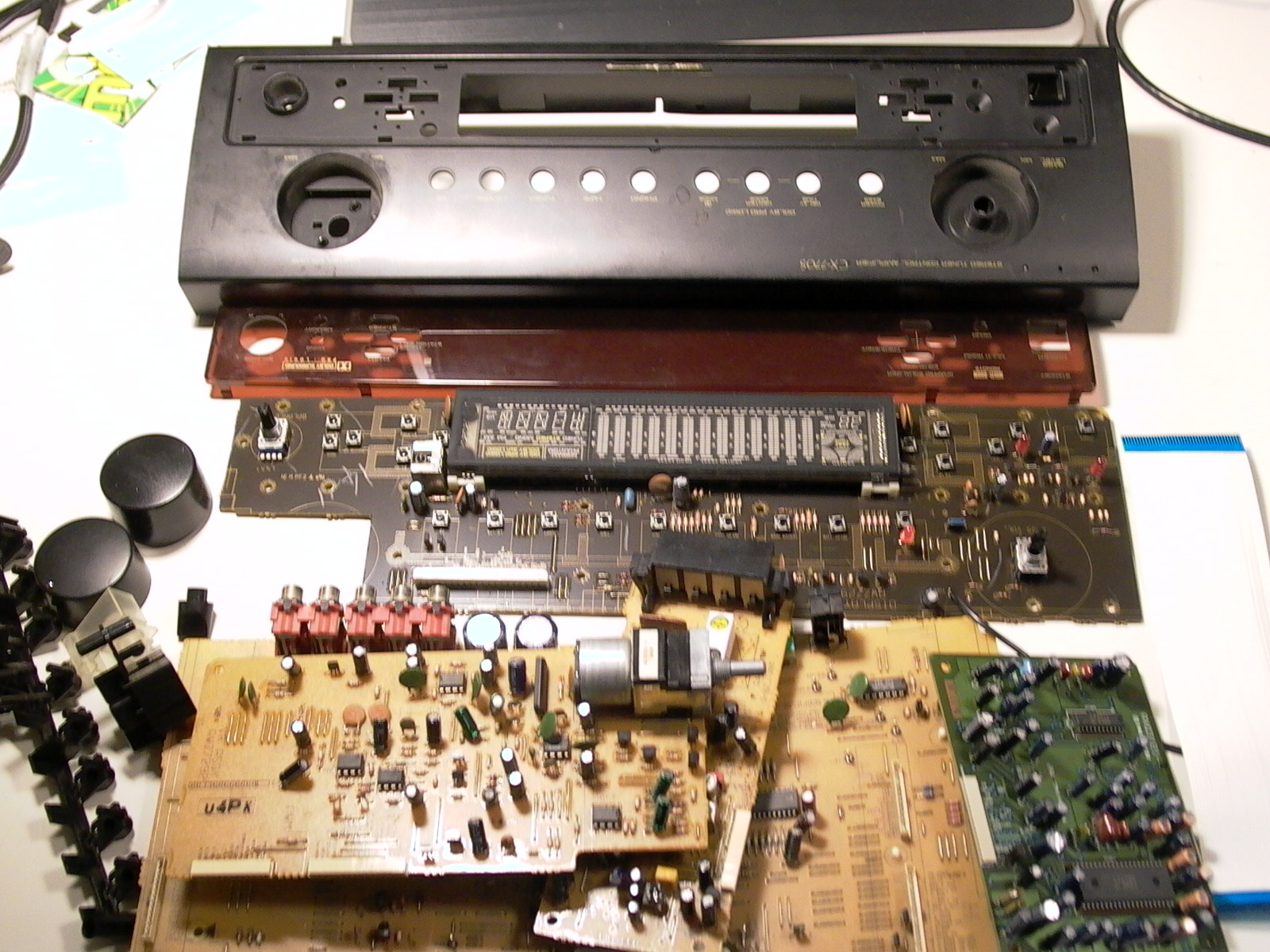
While waiting for the components to arrive in the mail, I began preparing by opening and gutting the interior of the Pioneer CX-770s. As the way in which an old piece of electronic gear is prepared for repurposing will vary according to your plans and the way in which the unit was originally designed, it is important to keep in mind that this article is NOT a “how-to” but instead meant to provide ideas and inspiration.
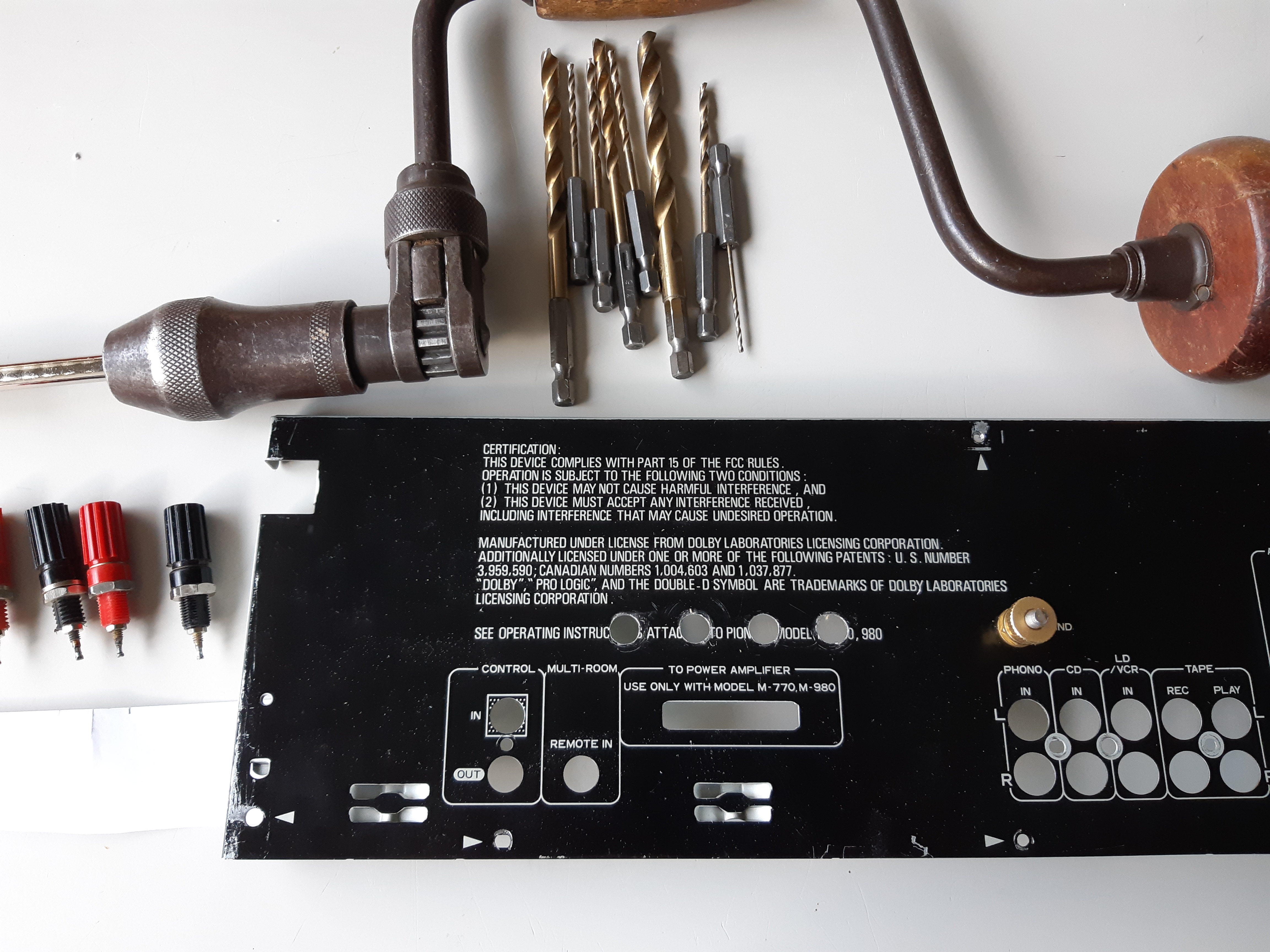
First, the original circuit boards as well as the plastic front panel were removed and tossed into the recycling bin while most of the back connectors were left in place, almost stripping the unit to its empty case.
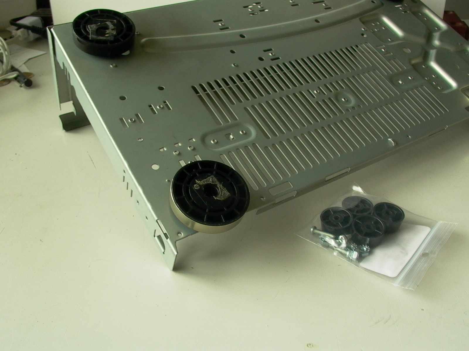
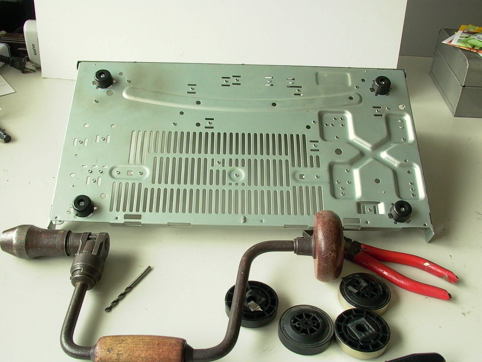
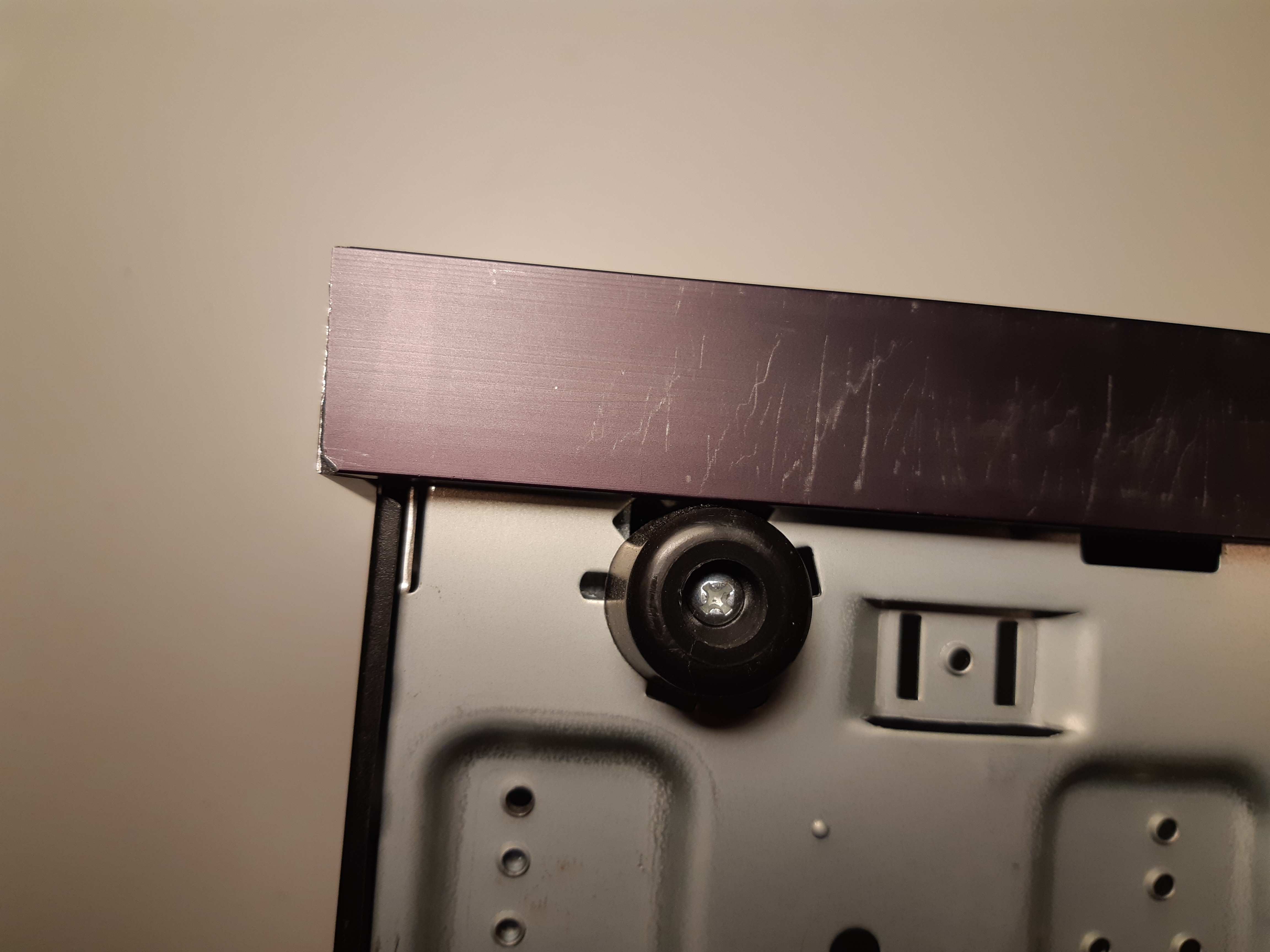
Once the case was gutted, I replaced the hockey puck-like feet with some decent looking albeit generic rubber feet. Hockey puck style feet were used on BPC stereos and are still common today but look out of place for my design. As the front feet had to be repositioned to accommodate part of the front panel, new holes had to be drilled to install them (done in later steps).
Building the Front Panel
The front panel consists of three pieces: the subpanel, which is mounted directly to the case/chassis, a top piece that will be painted and labeled, and a frame that wraps around the perimeter of the front.
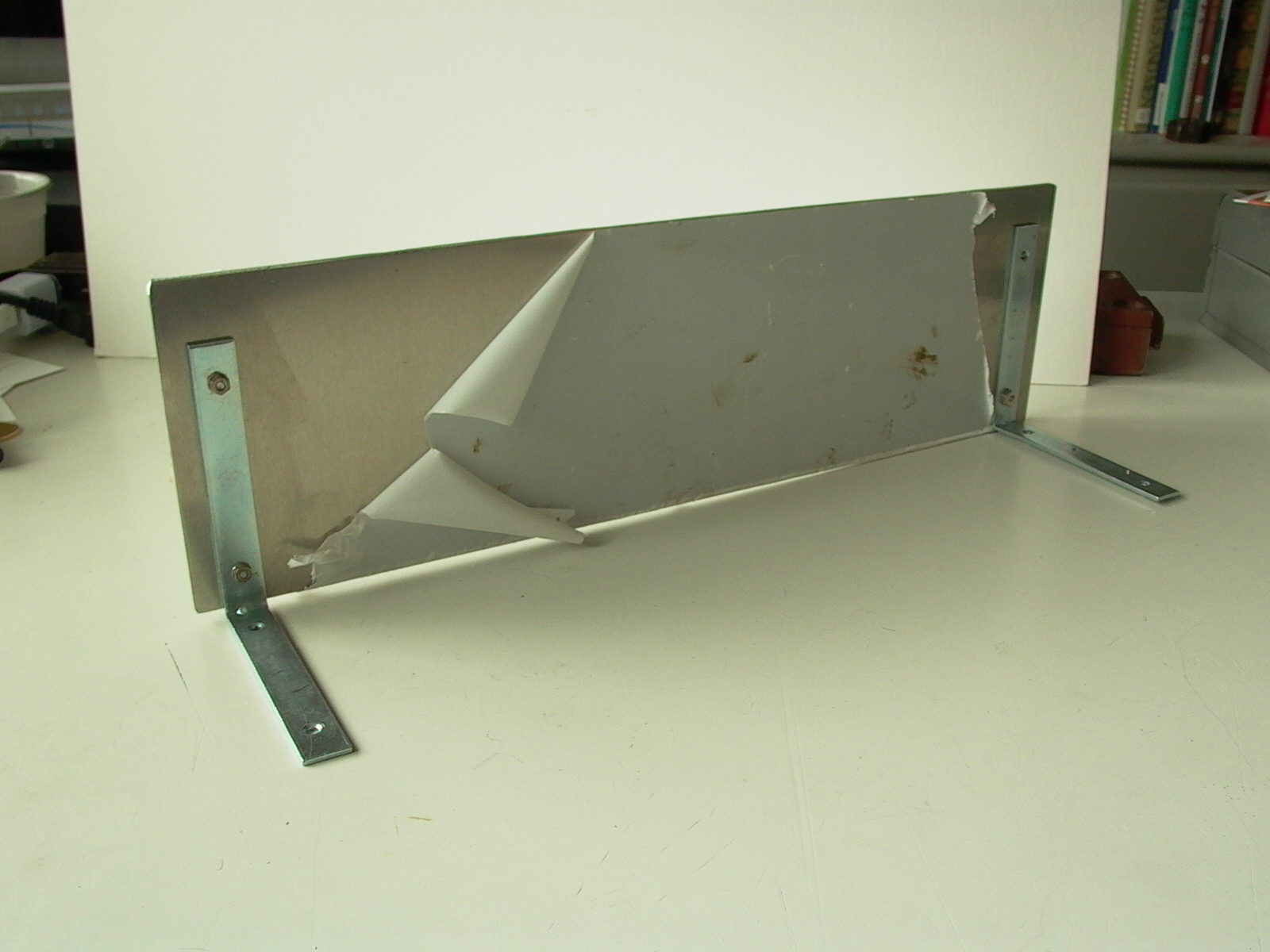
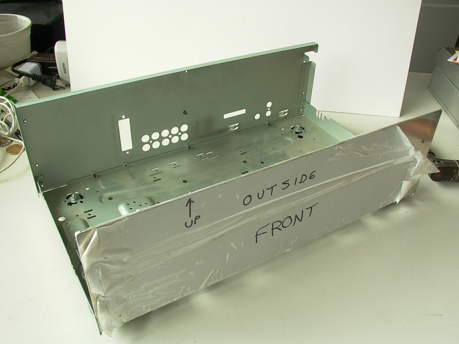
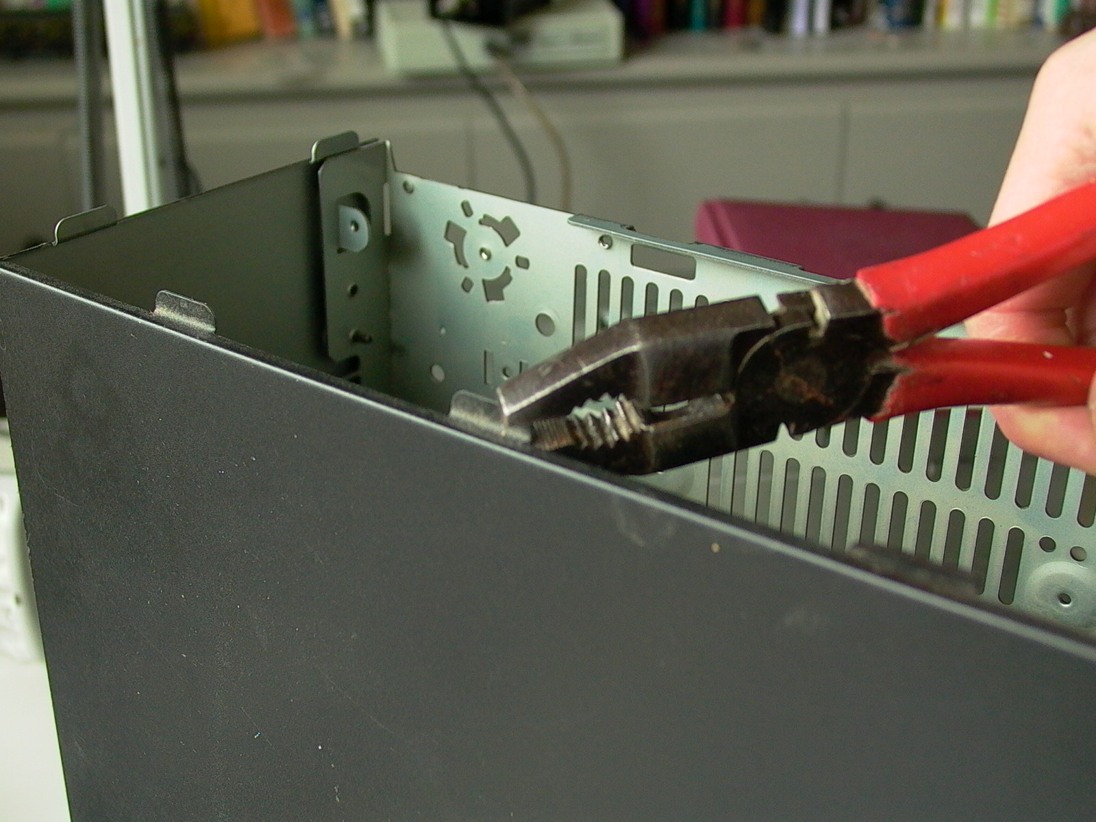
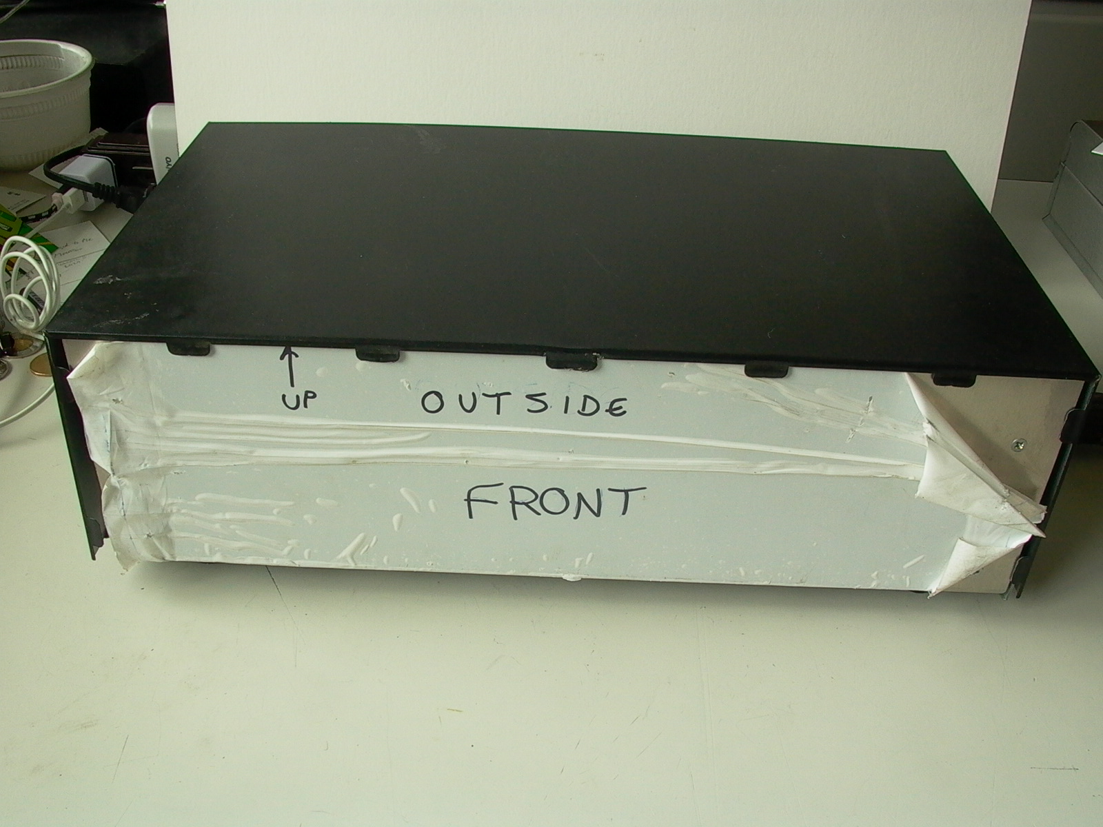
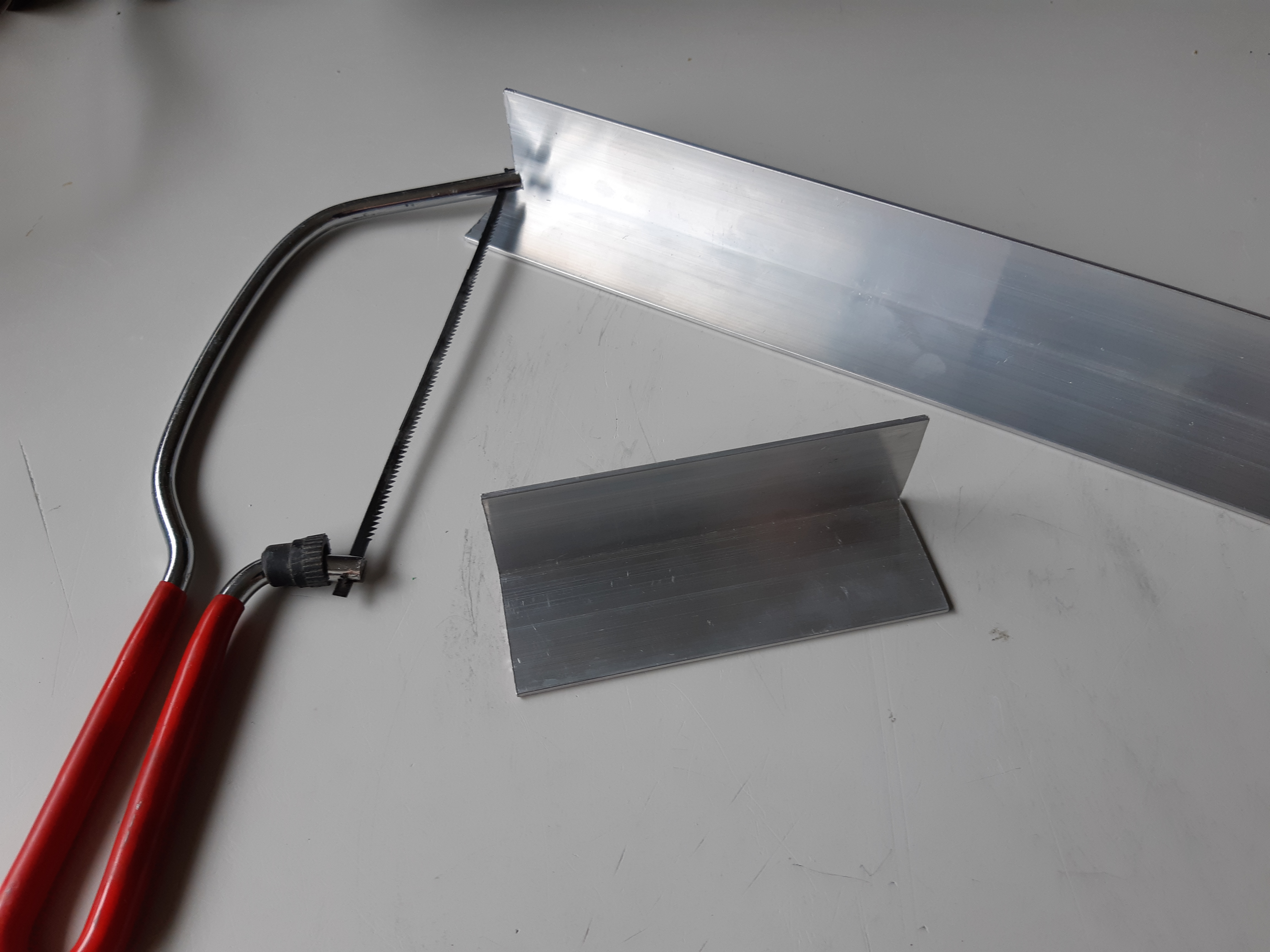
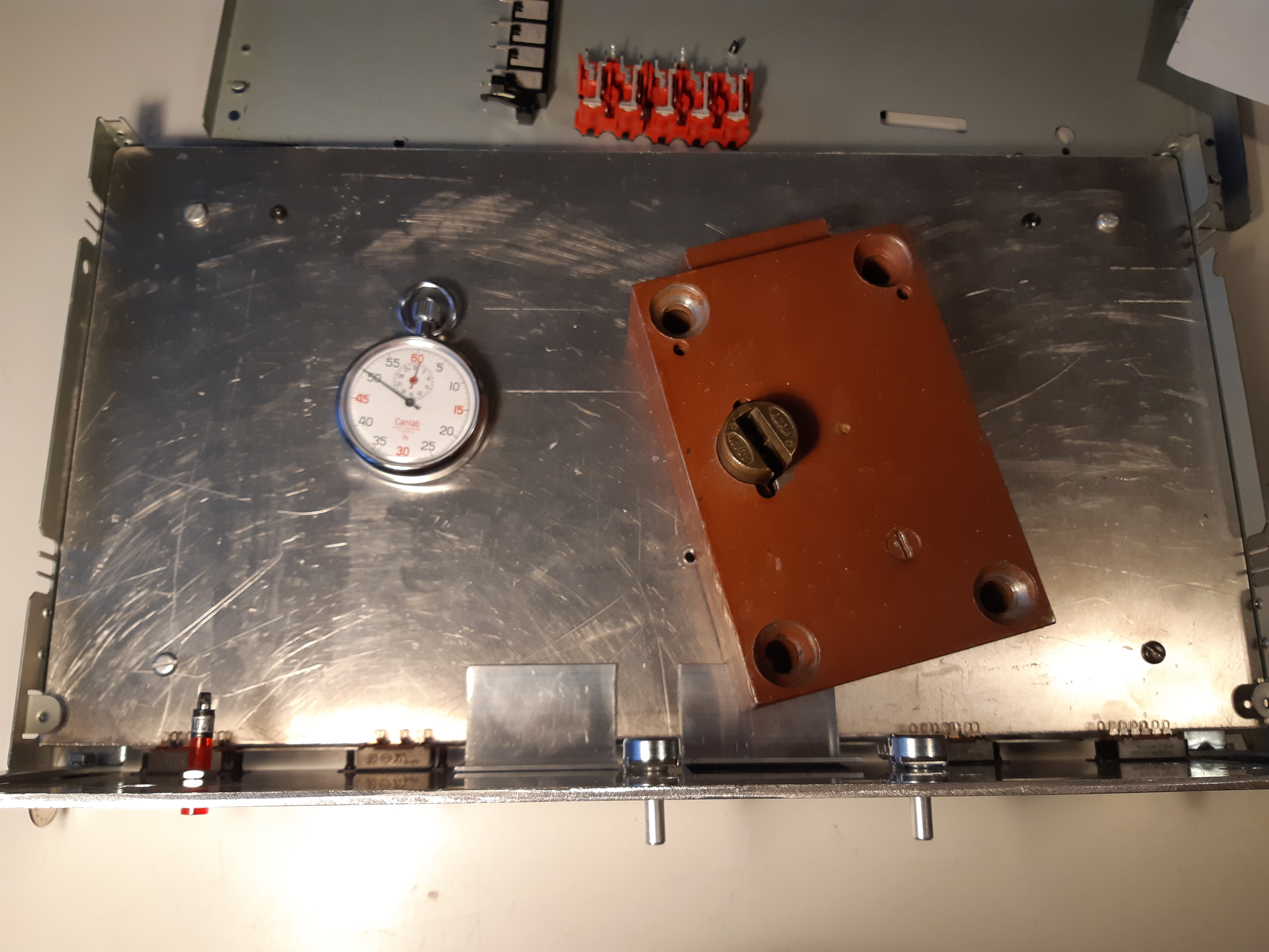
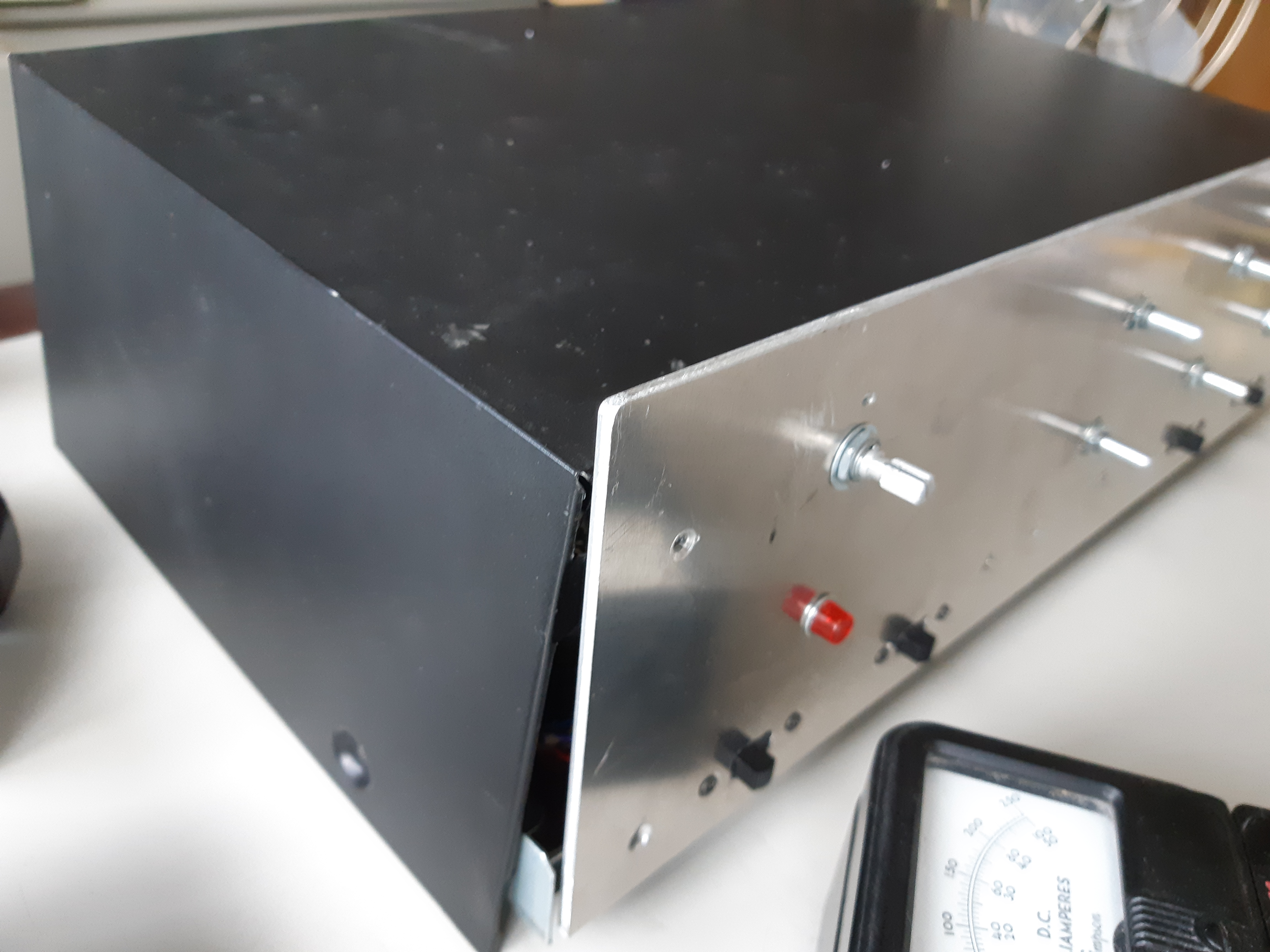
The sub-panel, cut from a sheet of aluminum 1/8″ thick by a local sheet metal shop, was of a width just few millimeters less than the width of the bottom piece of the case and of a height that would allow the top cover to cover the top edge of the panel. Angled brackets were temporarily screwed to the sub-panel (fig. 4) so that the bottom edge is flat on the surface when the panel is placed upright. The blank subpanel was then installed into the bottom piece (figures 5 and 7) and positioned so that the front surface is flush with the front edge of the top cover; again, this installation is temporary as it will be secured to the chassis by another means later. Note: before installing the front subpanel, tabs protruding from the front edge of the exterior top cover had to be flattened and bent downwards (fig. 6) in order to accommodate the piece as the tabs were originally used to attach the cover to the now-recycled black plastic front piece.
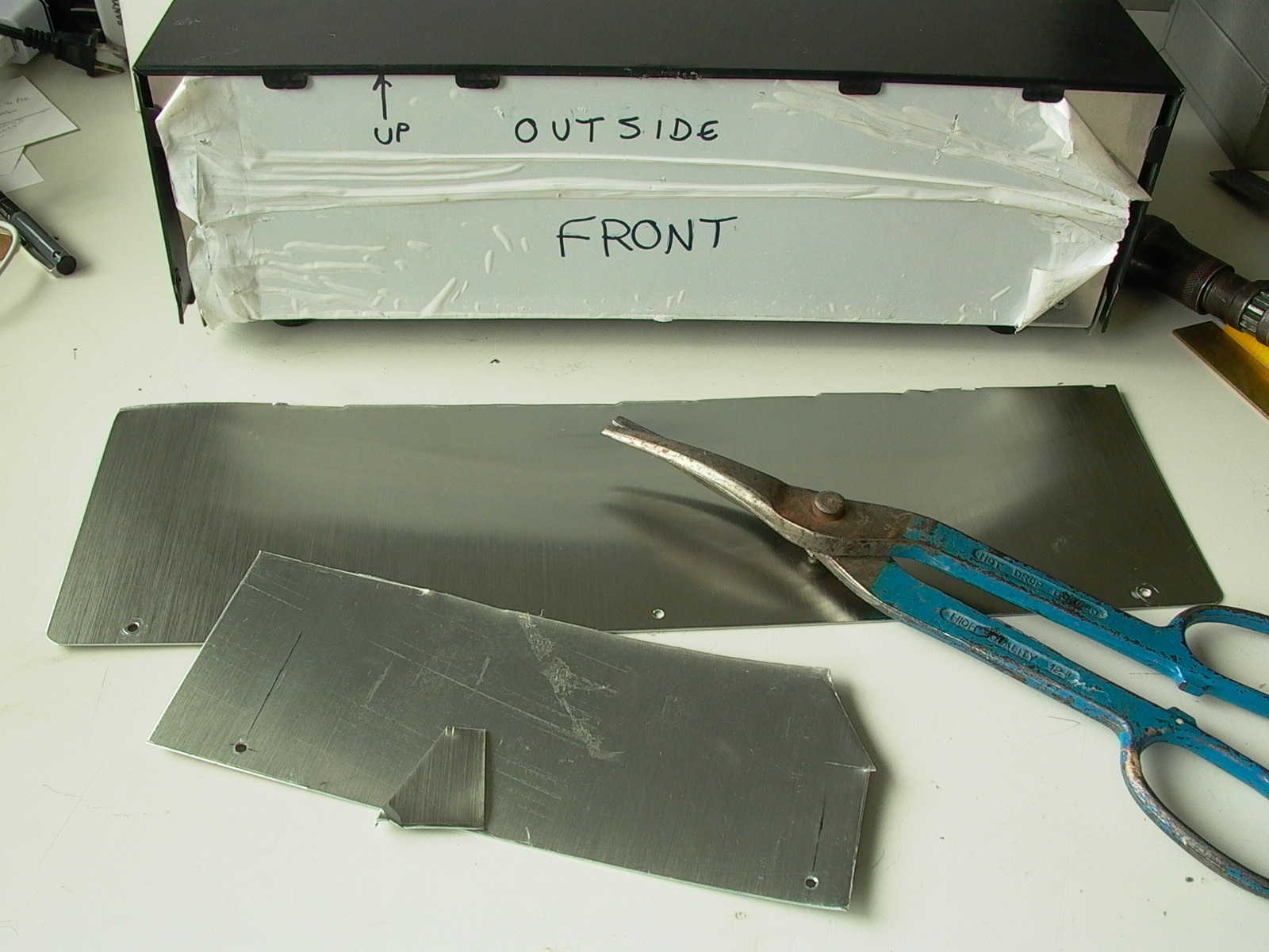
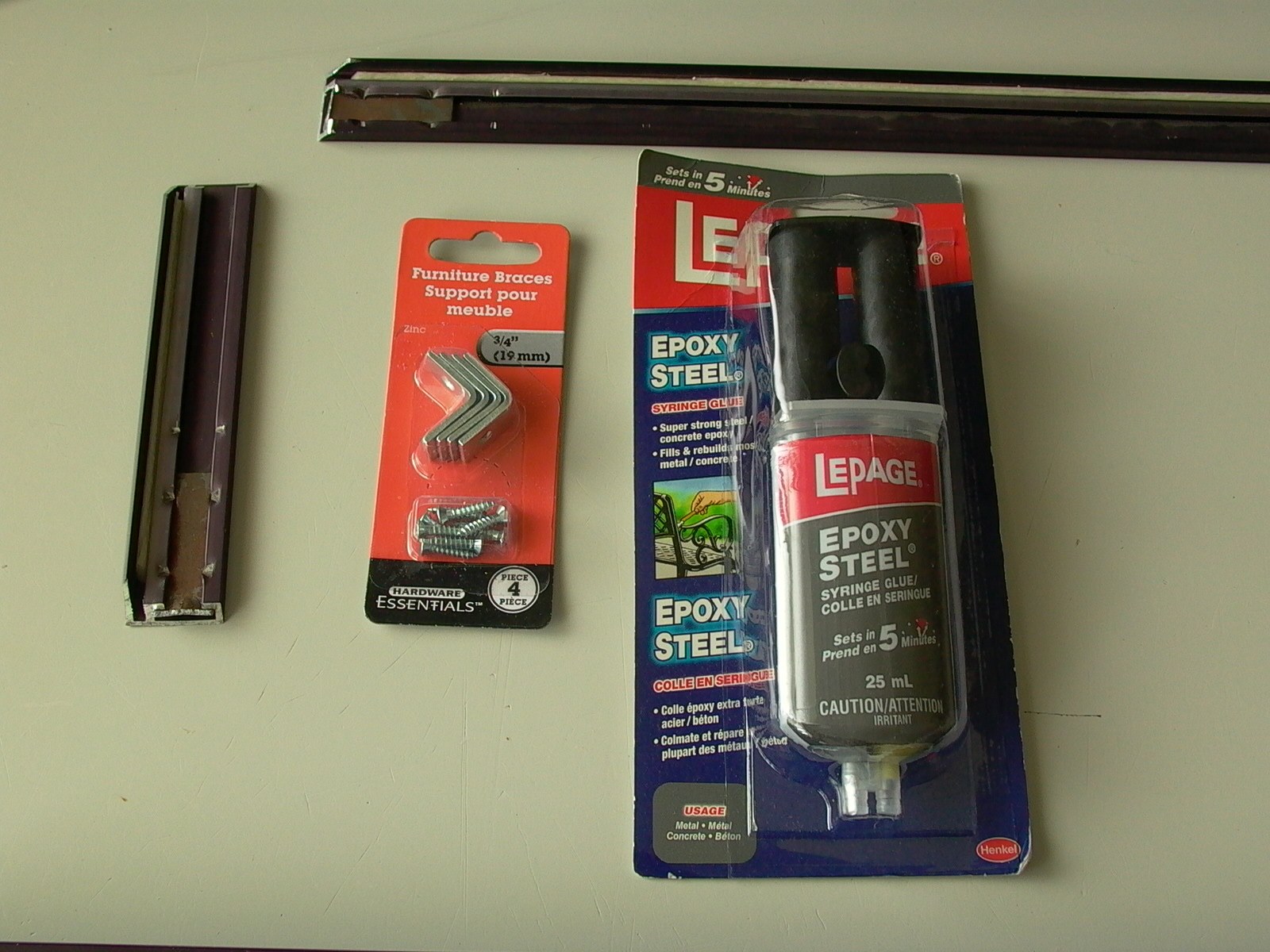
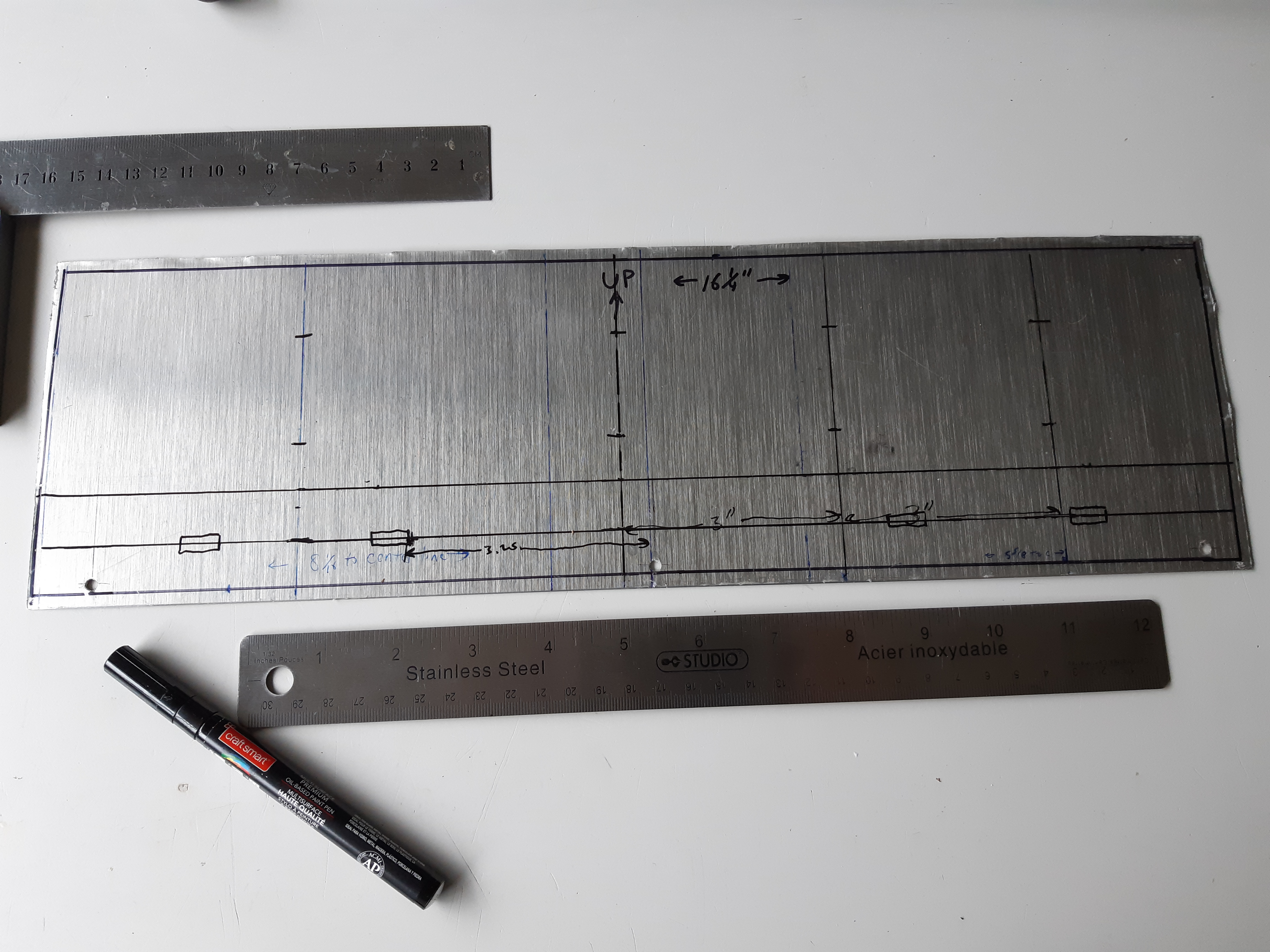
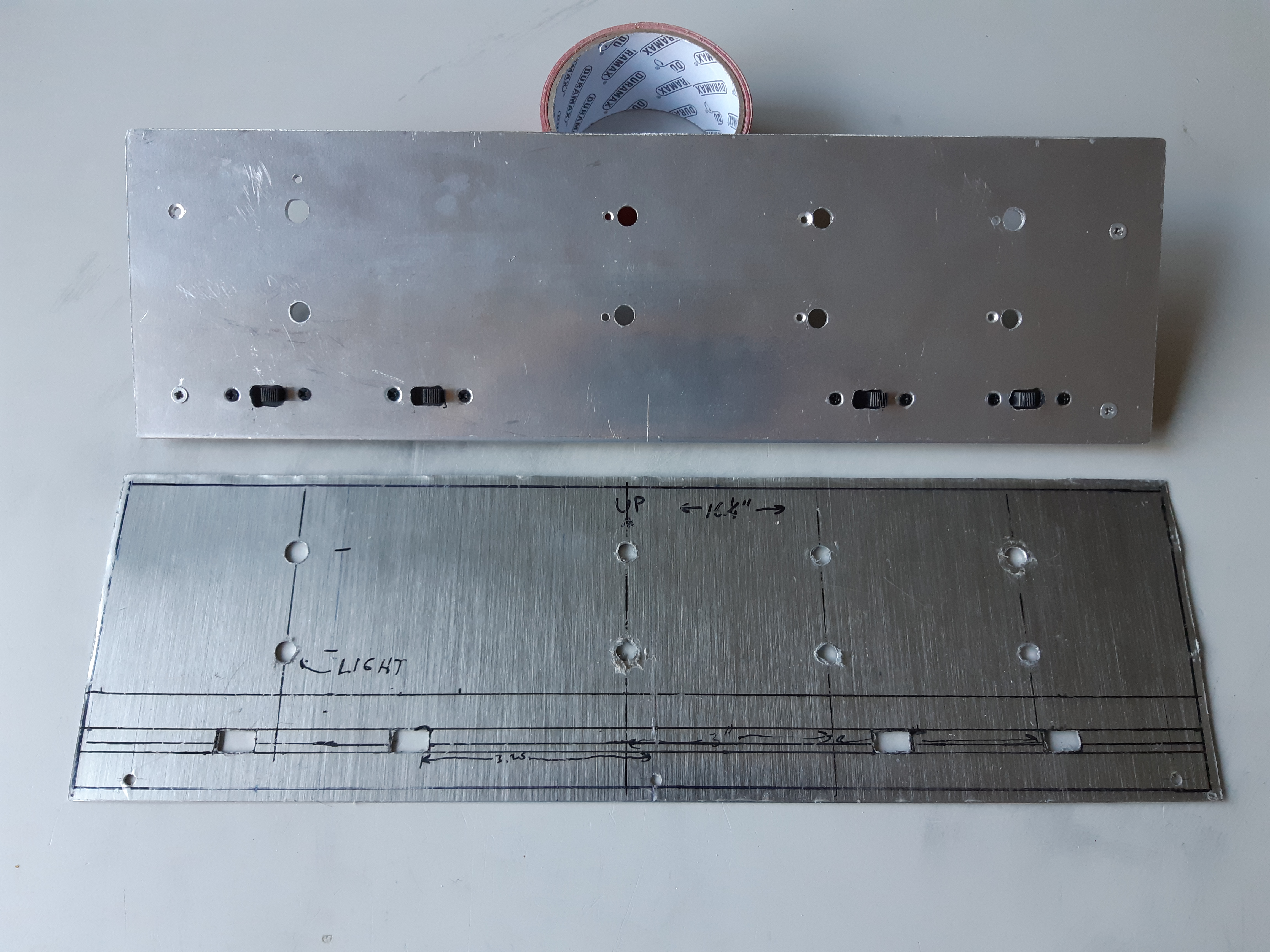
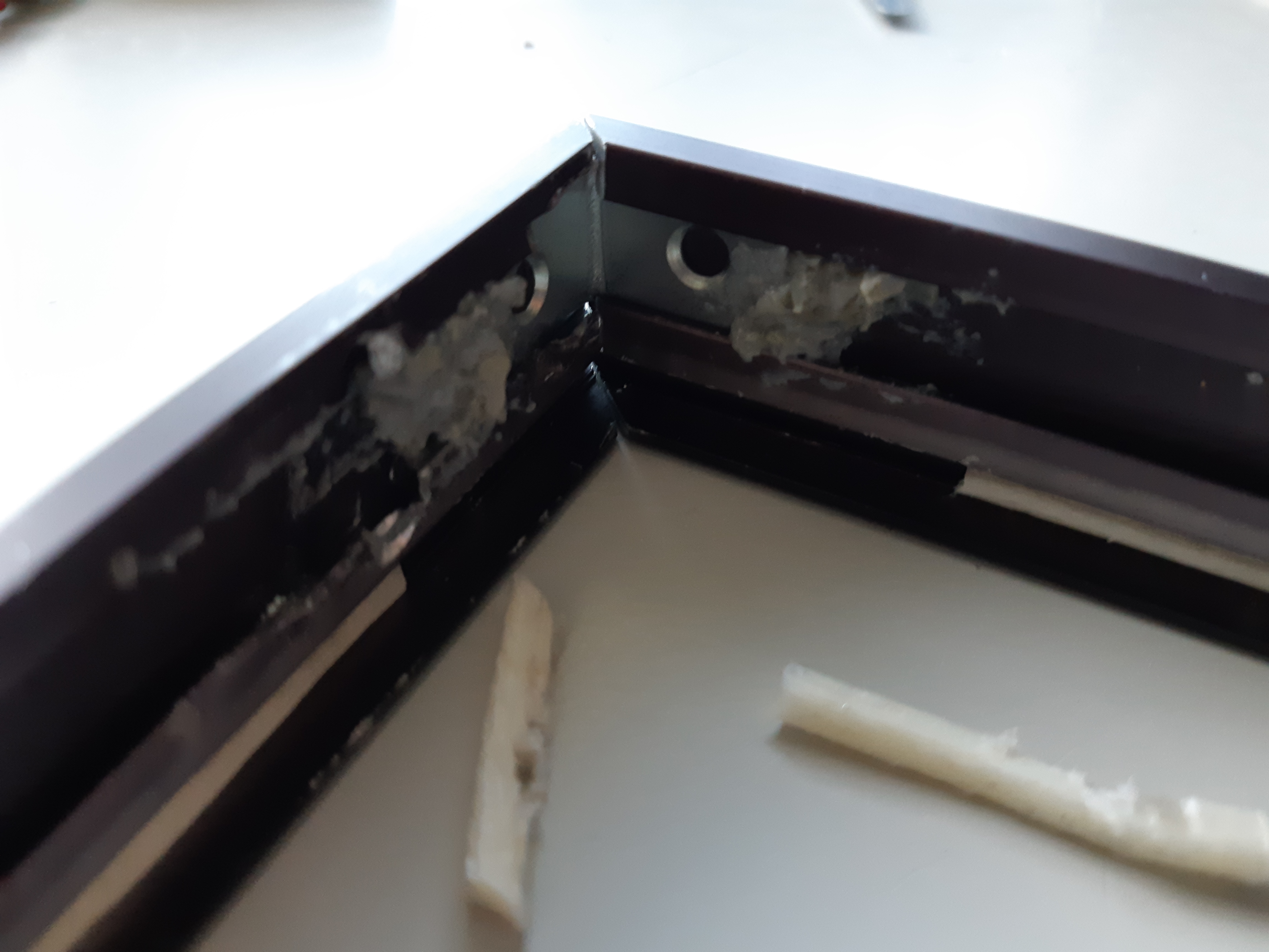
To make a blank for the outer piece of the front panel, a piece of aluminum was cut from a scrap sheet about 0.025″ thick to the same height as that of the sub panel but a little wider – as wide as the inside of the cover piece (fig. 8). As the outer piece of the front panel was cut from scrap, there were a couple of unwanted holes near the bottom but this would be solved later by filling with epoxy “steel” glue and painted over, resulting in an almost invisible fill. At this time, there is no way to install the outer panel as the piece is to be held together by the nut of the controls for which holes have not been drilled, and temporary screws are not an option as the piece is to be nicely finished.
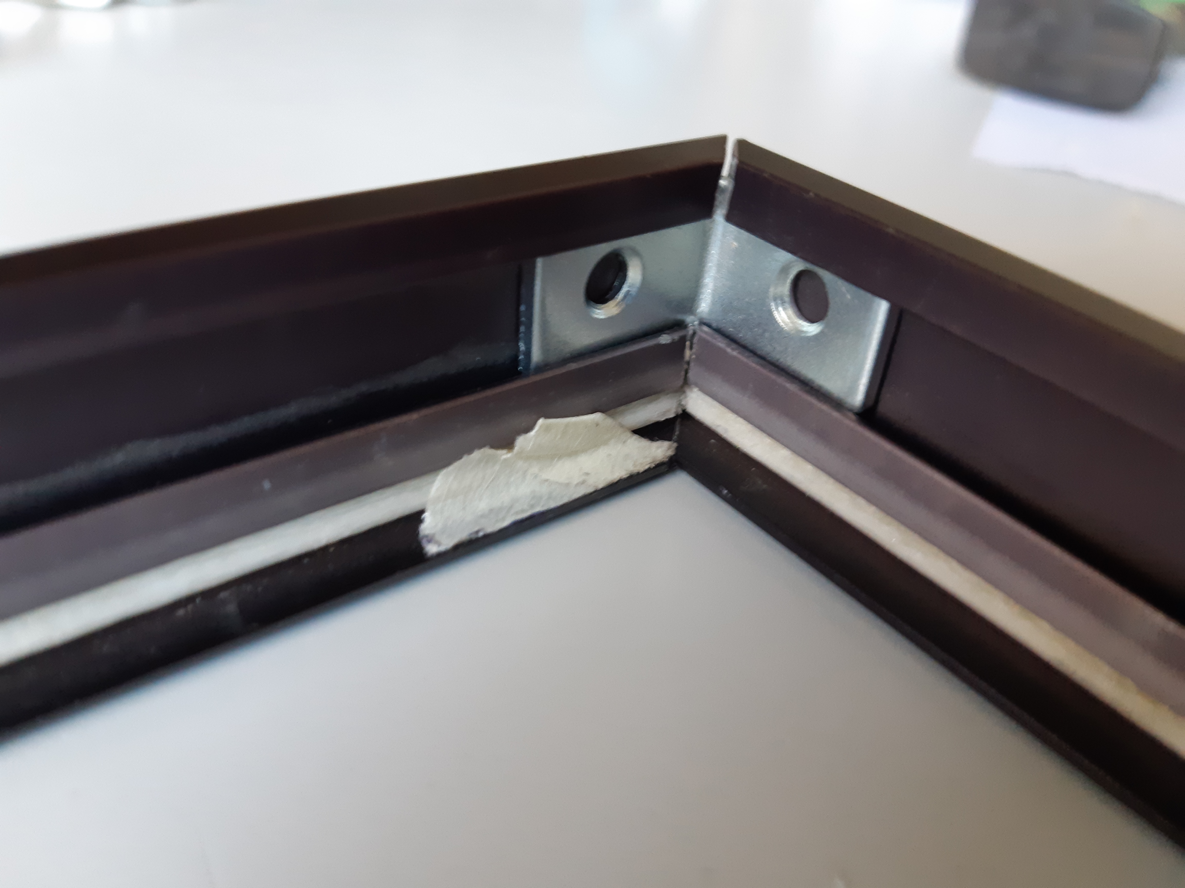
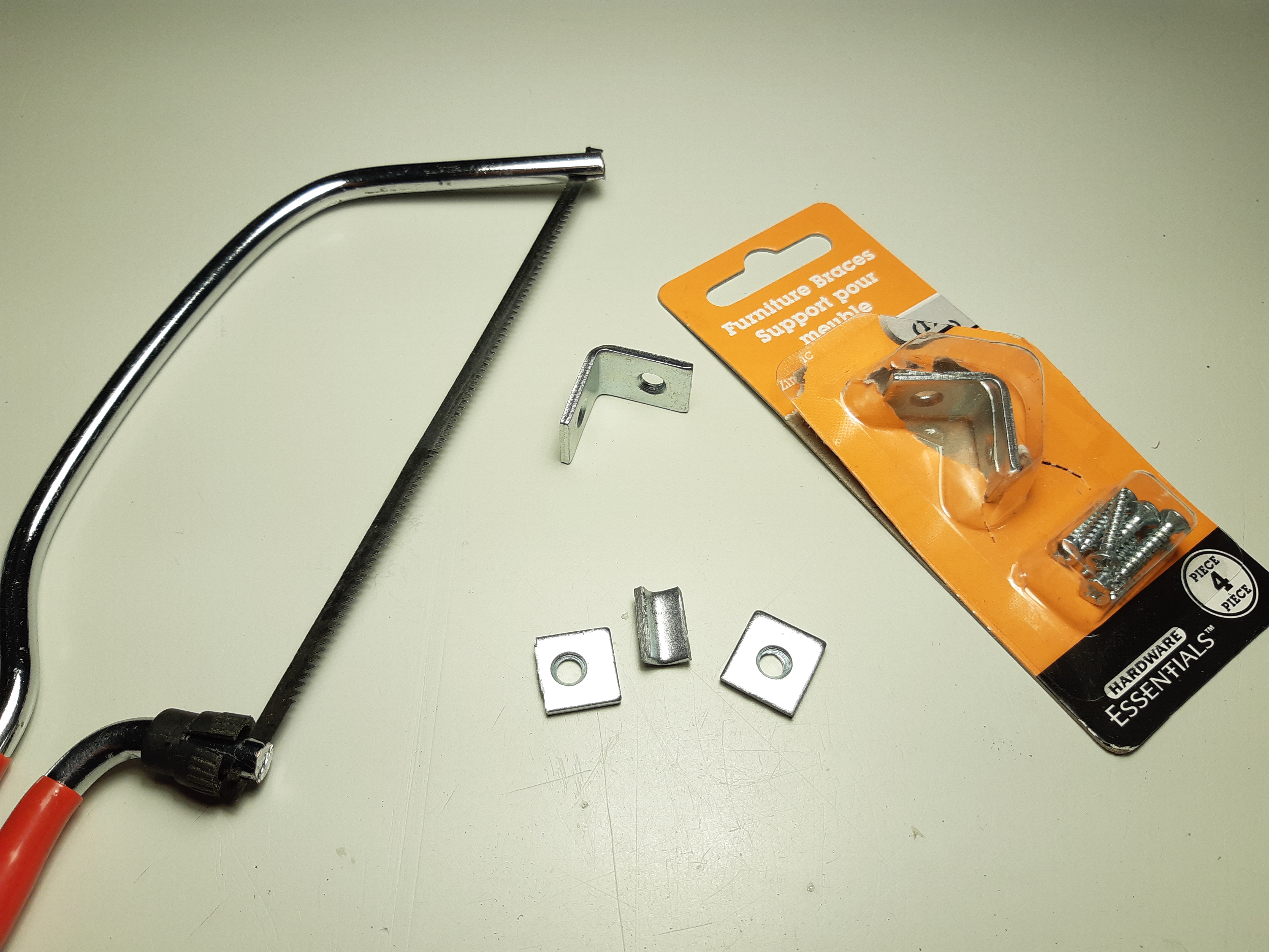
A frame for the outer edge of the front panel was made by resizing a plain modern aluminum picture frame from the thrift store. The type of frame you want to use for this project is known as a “back-loading” frame in which the back opening is almost the same size as the glass, allowing it to fall in and out of the frame. Measurements were taken using the back panel (fig. 9) and cut to size (fig. 10). The pieces were then assemble by inserting right angle brackets and securing them in place with epoxy “steel” (if available, I recommend JB Weld epoxy steel) (figures 11 to 13).
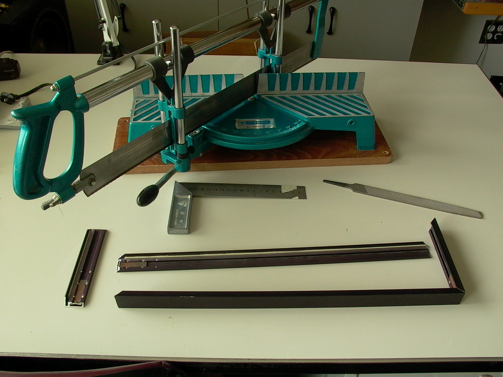
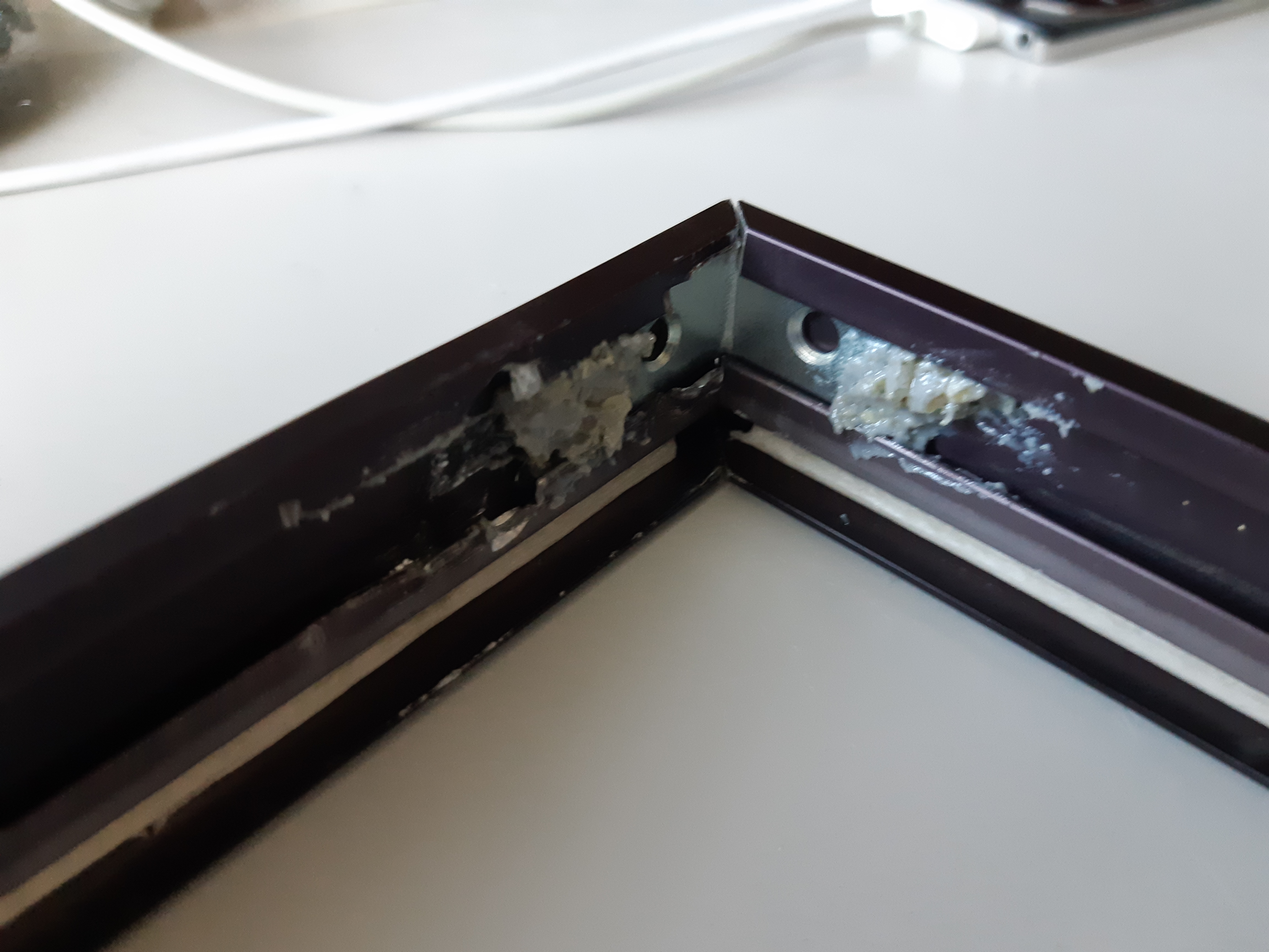
Notice how the frame in figure 9 is aluminum while in figure 10 is black? Yep, I screwed-up on the measurement by getting the outer and inner edges mixed up and had to go back to the thrift store to buy another frame. Fortunately, this style is very common (perhaps as common as BPC’s and other 90’s junk) but I should take the opportunity to remind everyone to MEASURE TWICE and cut once! Sorry for the bad chiché but you’d be surprised how simple things are often overlooked.
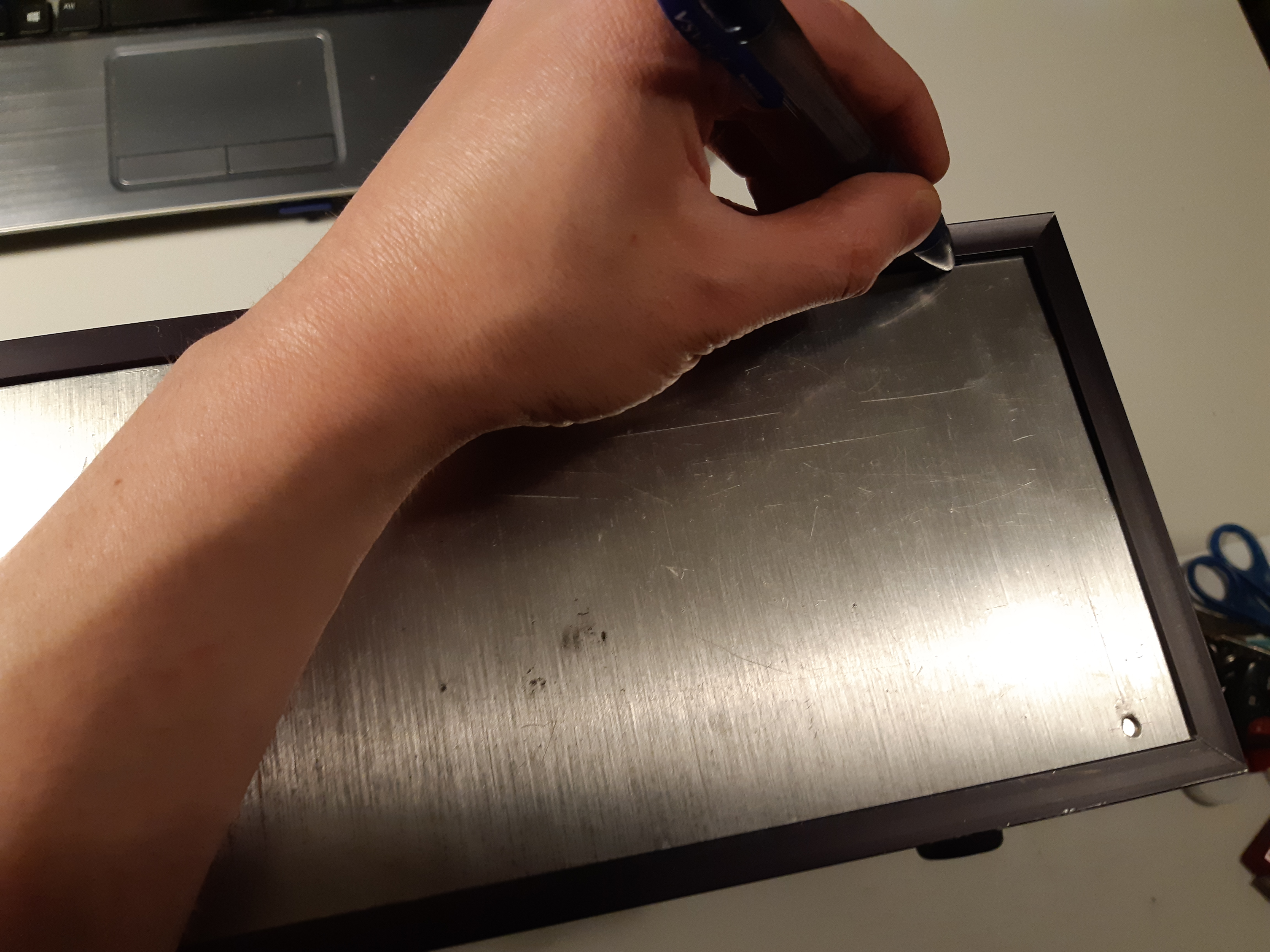
When frame was assembled, it was time to drill the front panel pieces. The outer panel was placed over the subpanel with the frame holding the pieces in place, and a fine paint pen was used to trace the inner edge of the frame (figures 14 and 15). As shown in figure 16, I have run into a small problem with the front feet and will thus have to be move to a different spot later.
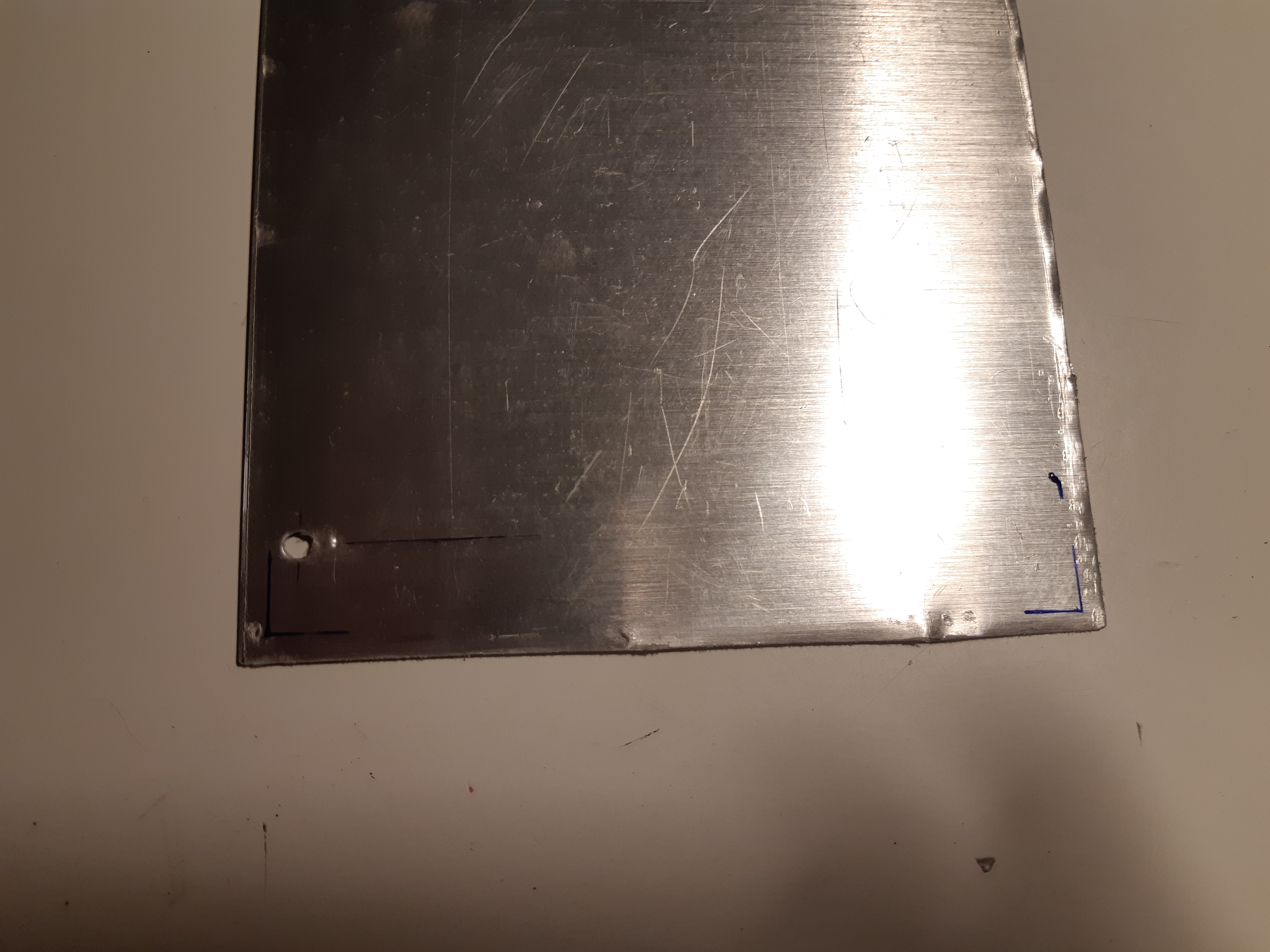
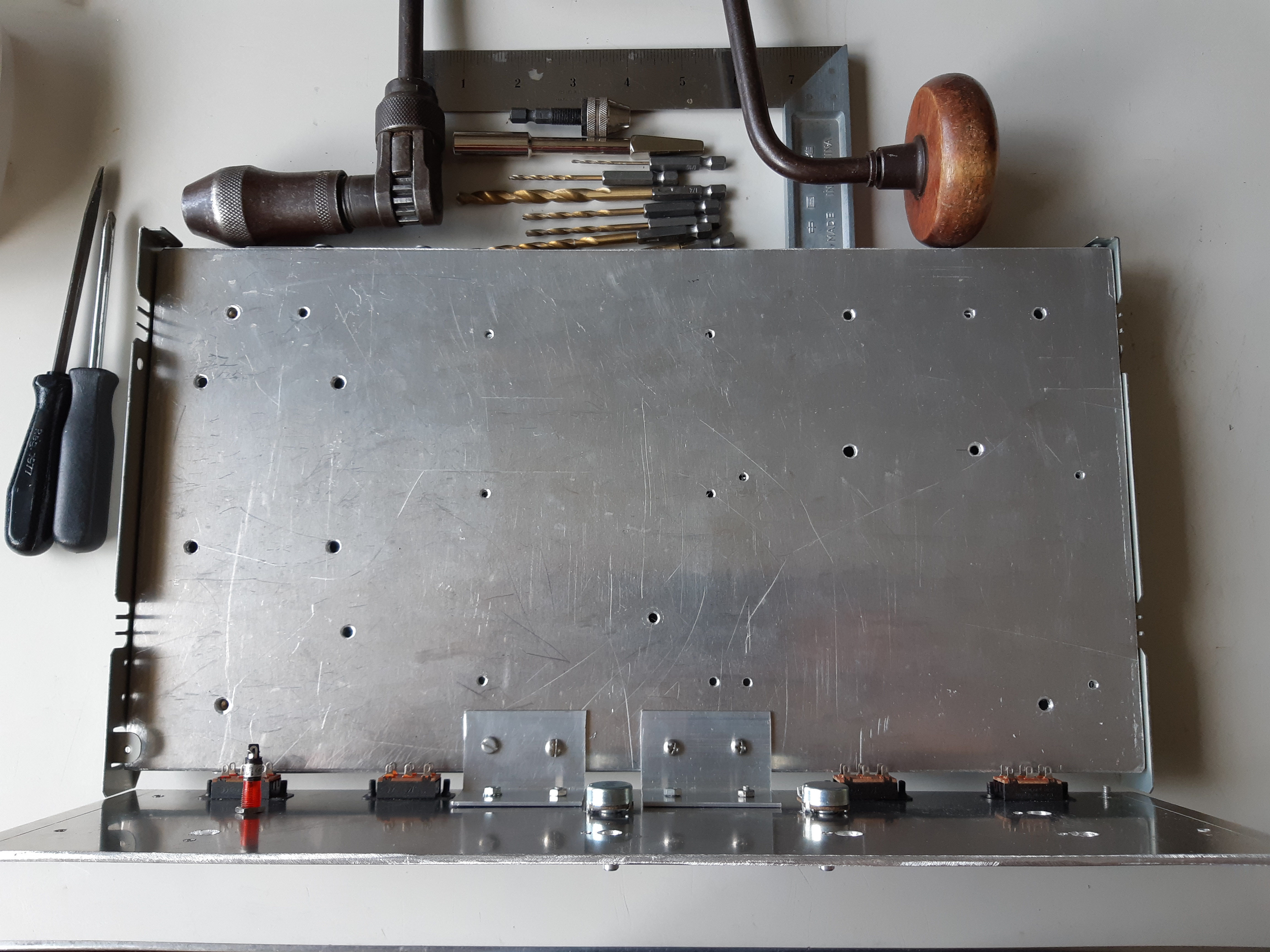
The outer front panel was then removed from the case and was marked for drilling (figure 17). Each channel, left and right, will have its own independent knobs for bass, treble, and volume for a total of six separate dials, and a single rotary input selector switch for both channels. There will also be a hole for a power-on light and along the lower part of the front panels, slide switches for power, stereo/mono selector, stereo reverse, and speaker phase reverse. The slide switches require rectangular holes.
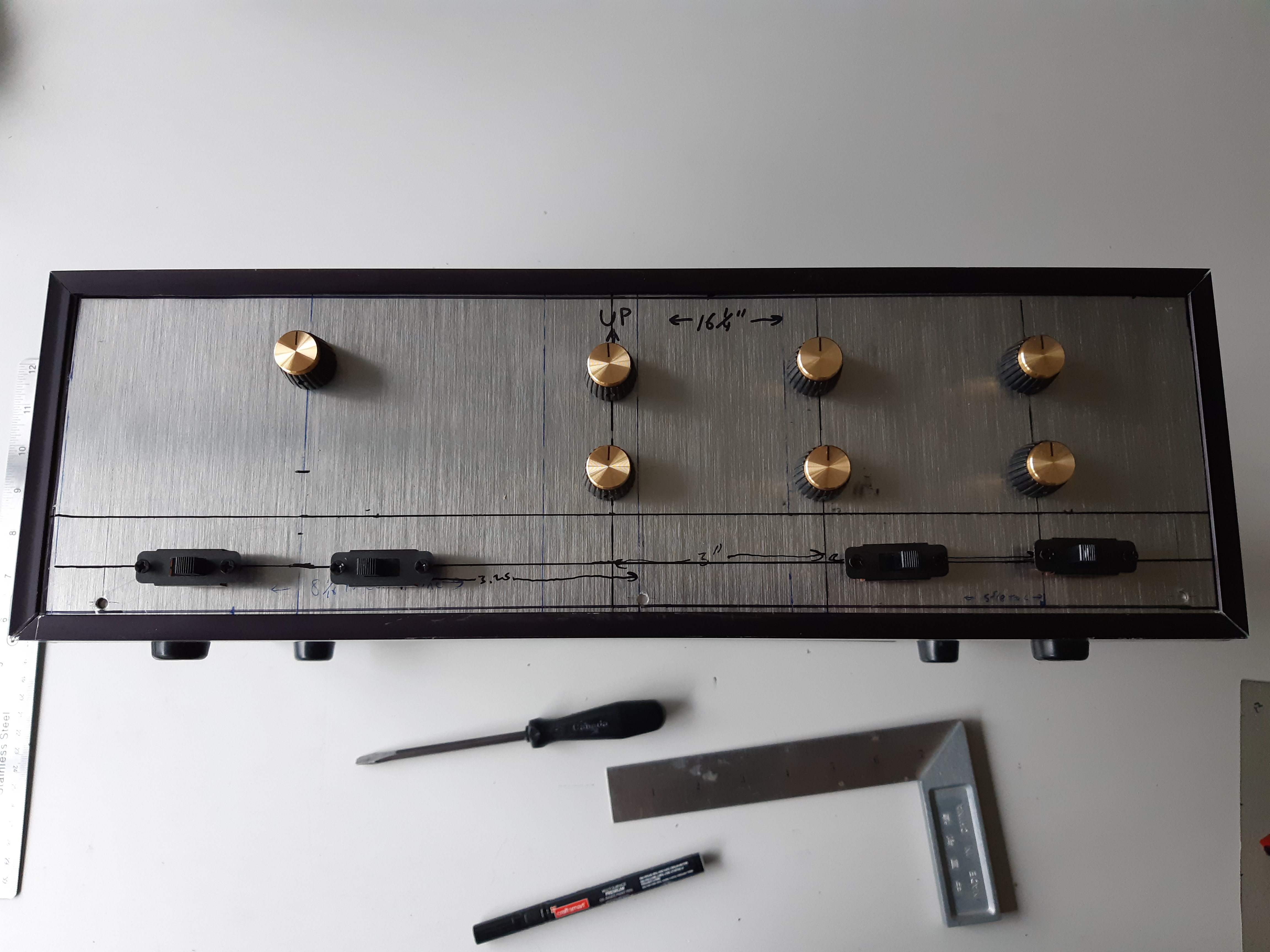
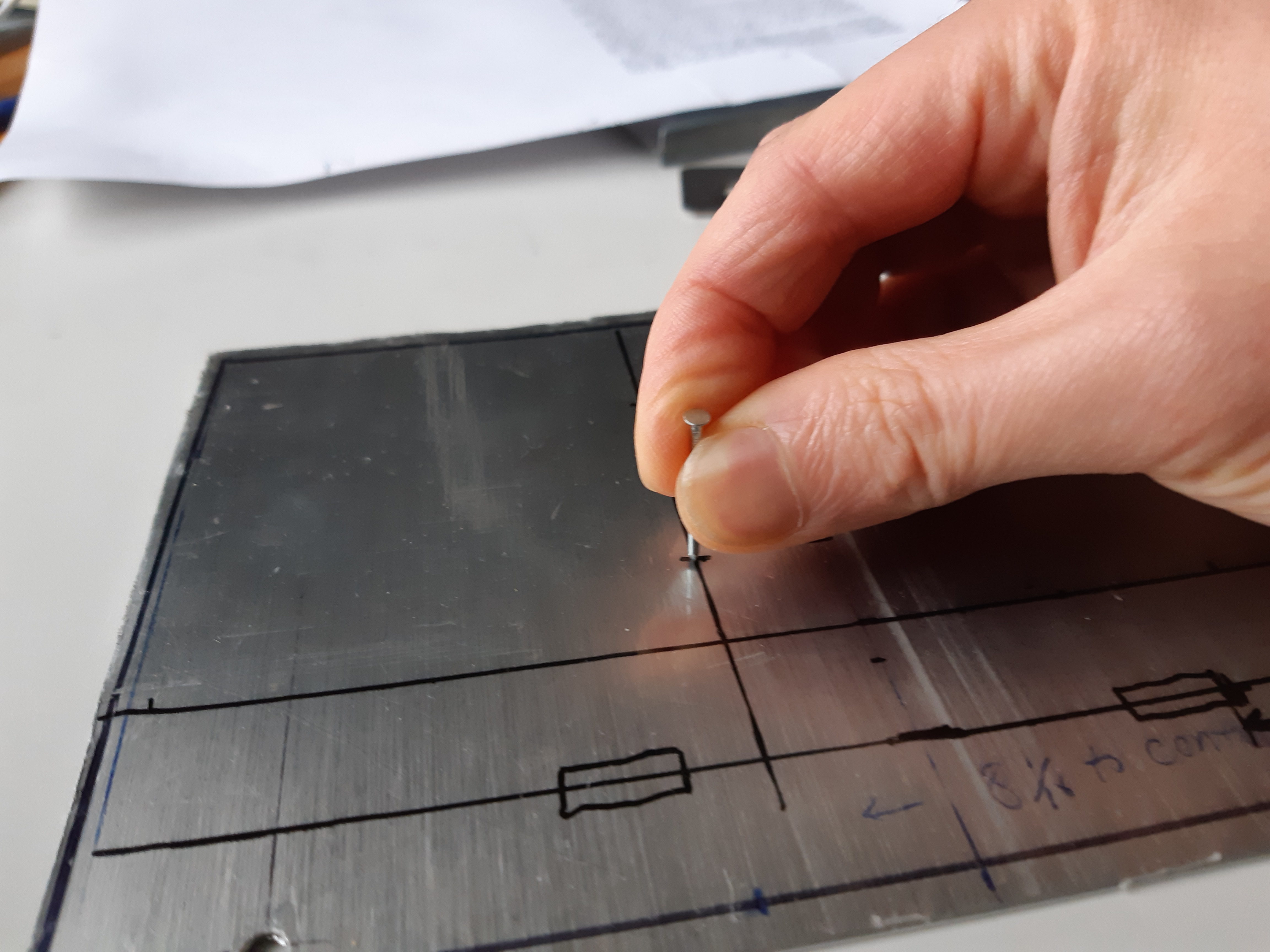
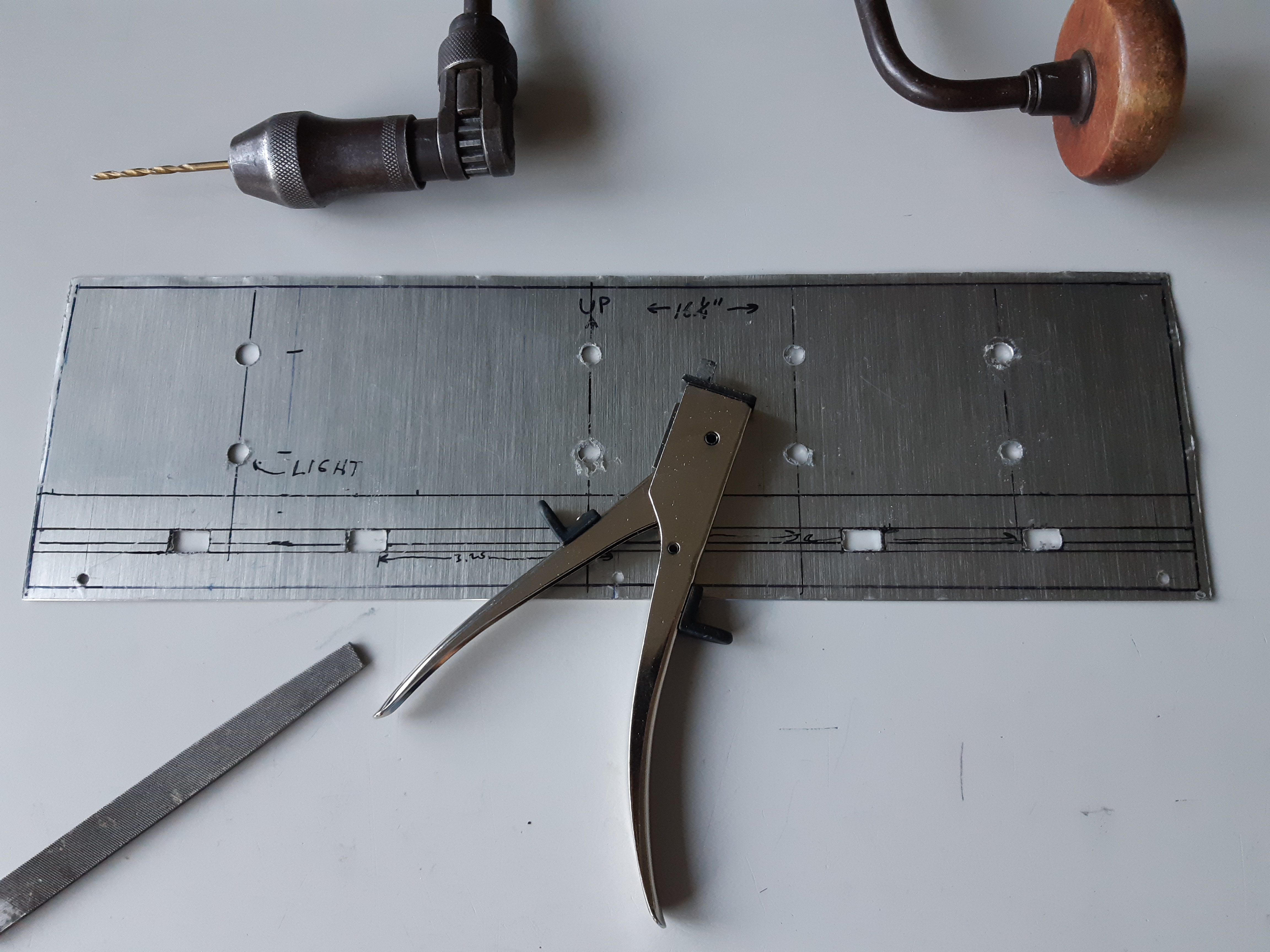
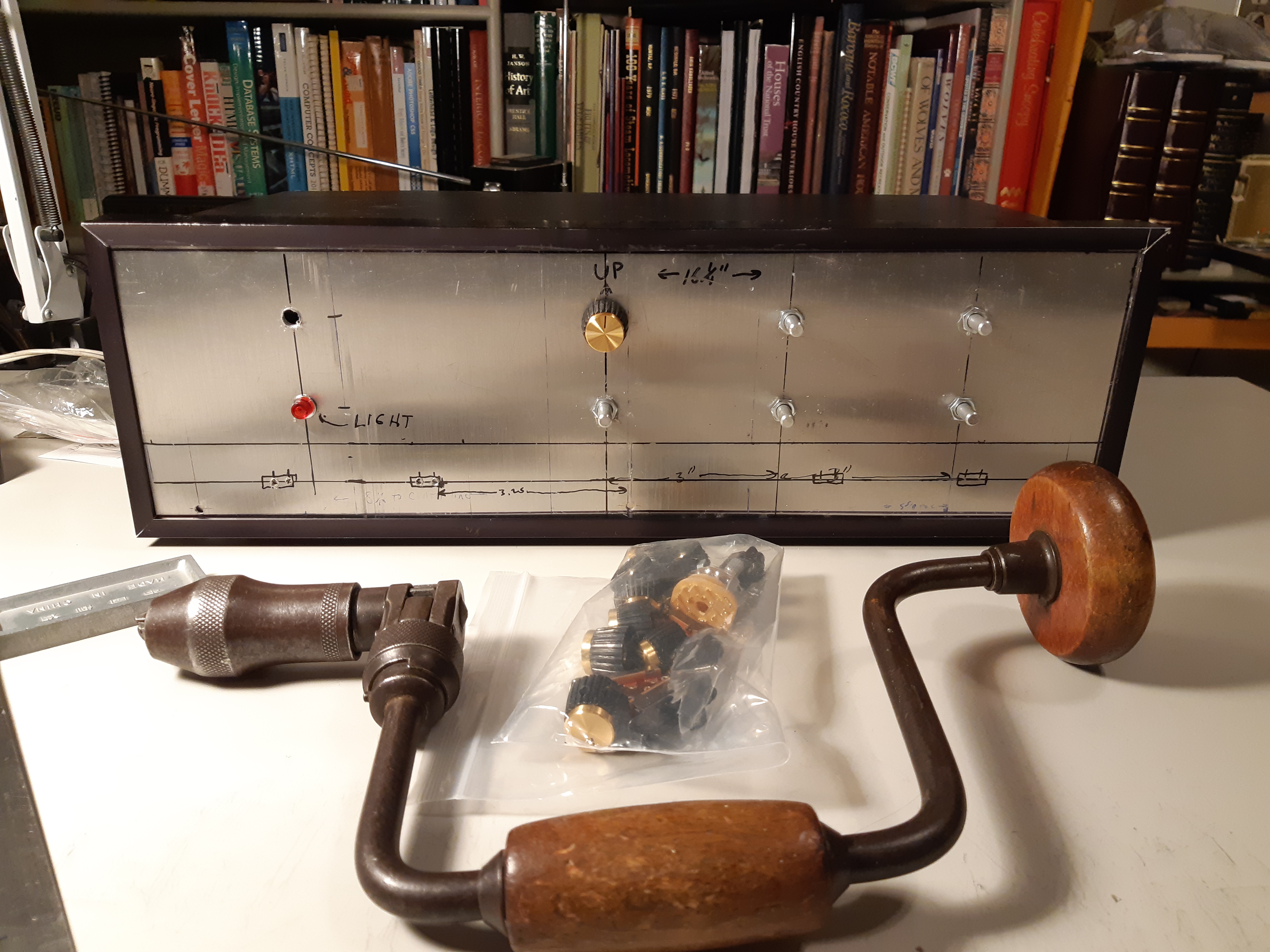
Just before drilling, the panel was placed back on the front with its frame in place and knobs and switches were placed over the dill points (fig. 18) to see how it would look. To guide the drill precisely, the panel was the removed from the case and each drill point was dented with a nail and a single strike of a hammer (fig. 19). The panel was put back in place and both the outer panel and subpanel were drilled together to ensure the position of holes align perfectly. For the rectangular holes, round holes were first drilled together through the outer panel and subpanel together. Then, the outer panel was removed and a nibbler was used to make them rectangular. The subpanel, however, was too thick for the nibbler and thus, a rasp was used to file the holes. Rectangular holes were then tested by installing the slide switches (fig. 21).
The volume and tone control knobs can now hold the outer panel securely in place (fig. 22).
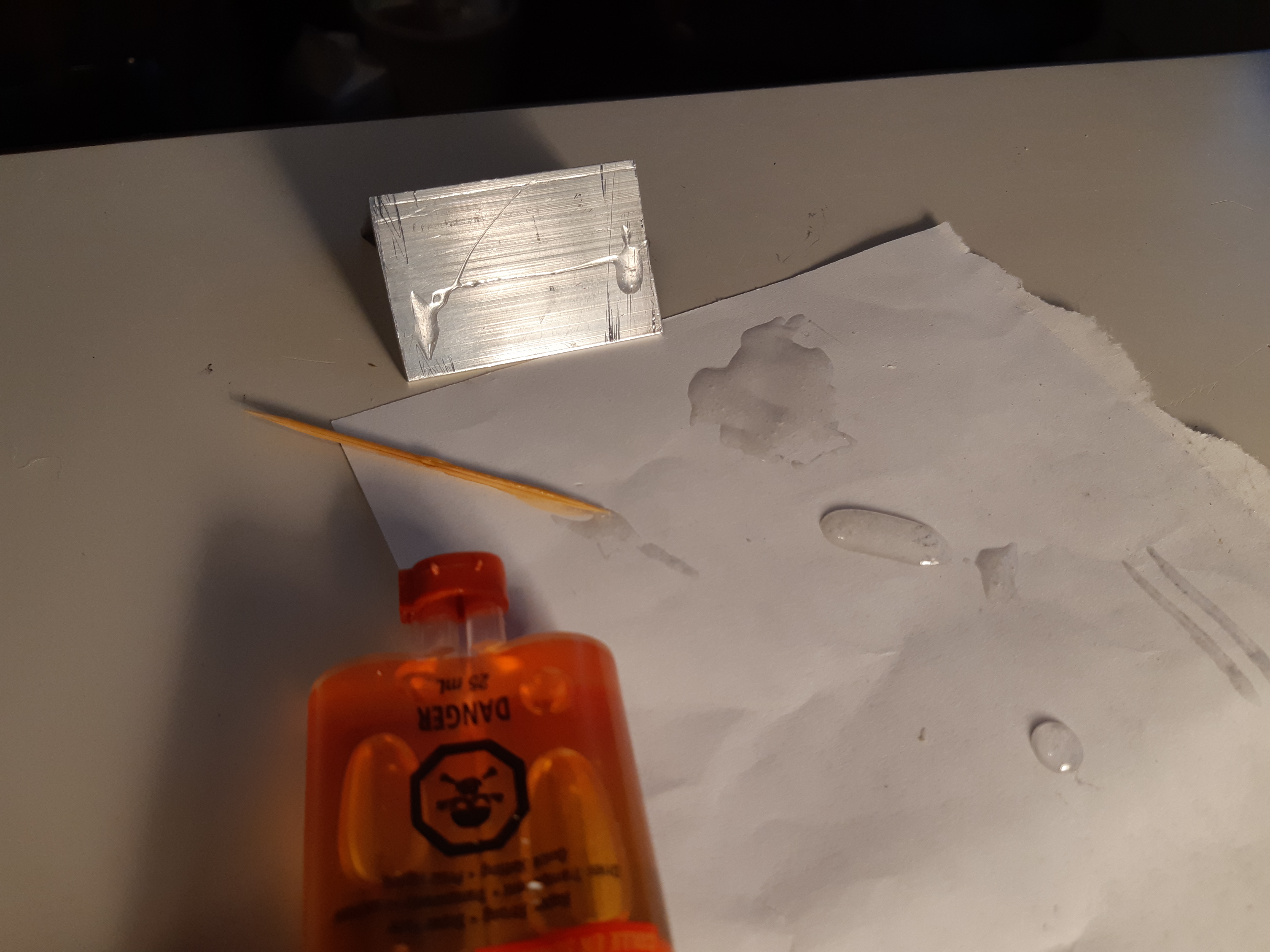
Unwanted holes were then filled. This can be done using epoxy glue but I recommend epoxy steel such as JB Weld if possible. In my case, I used LePage Epoxy Steel as it was the only type that was available at the time (fig. 23).
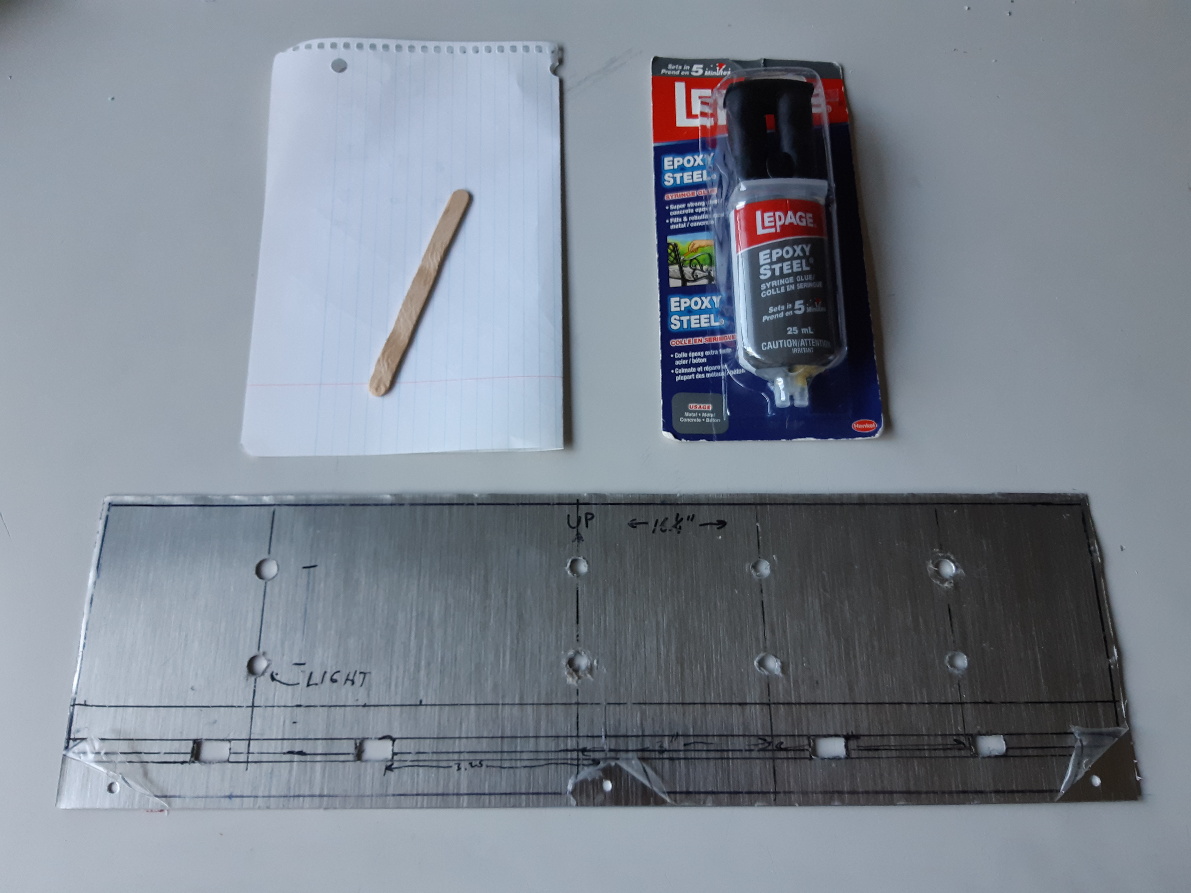
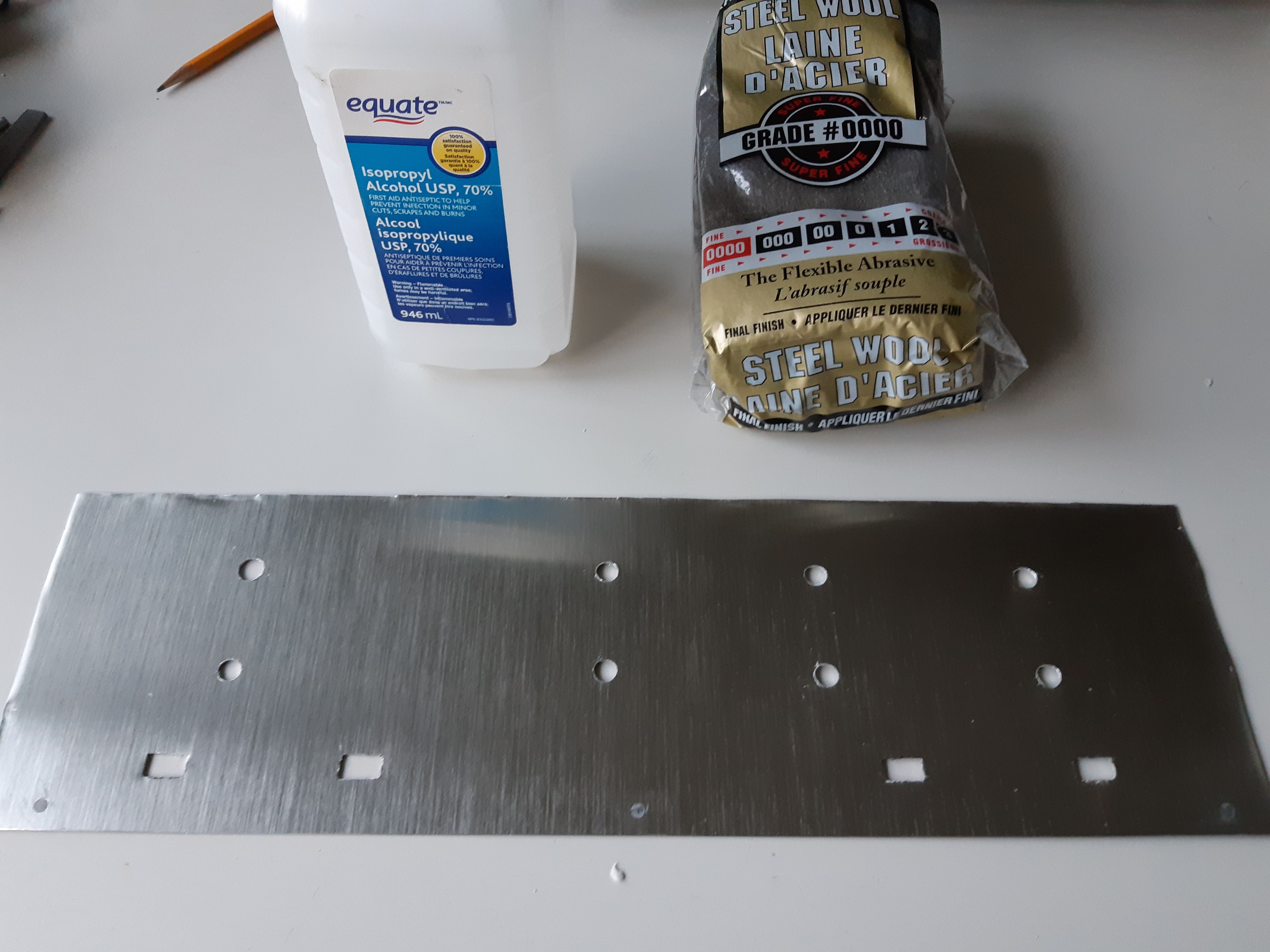
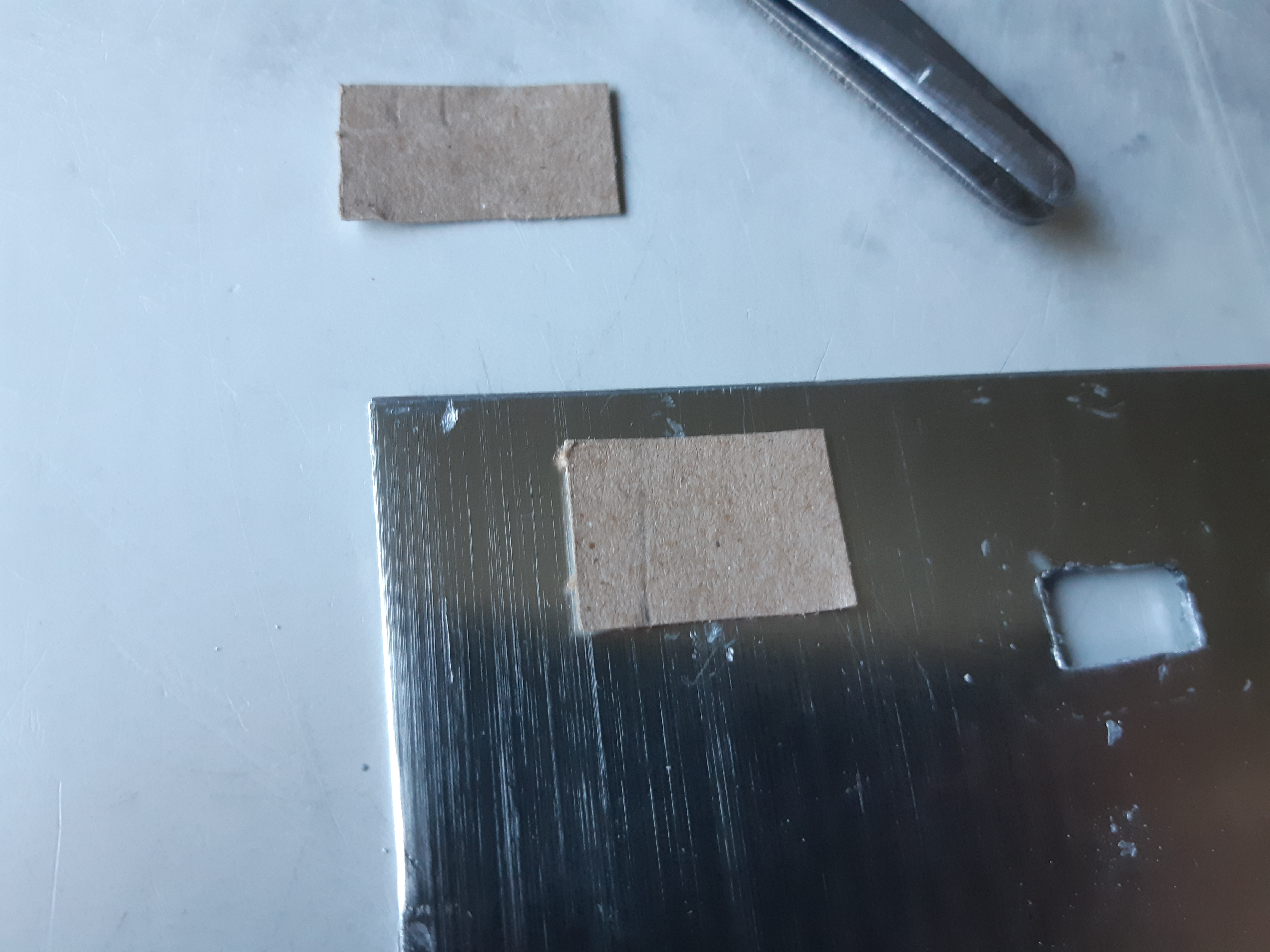
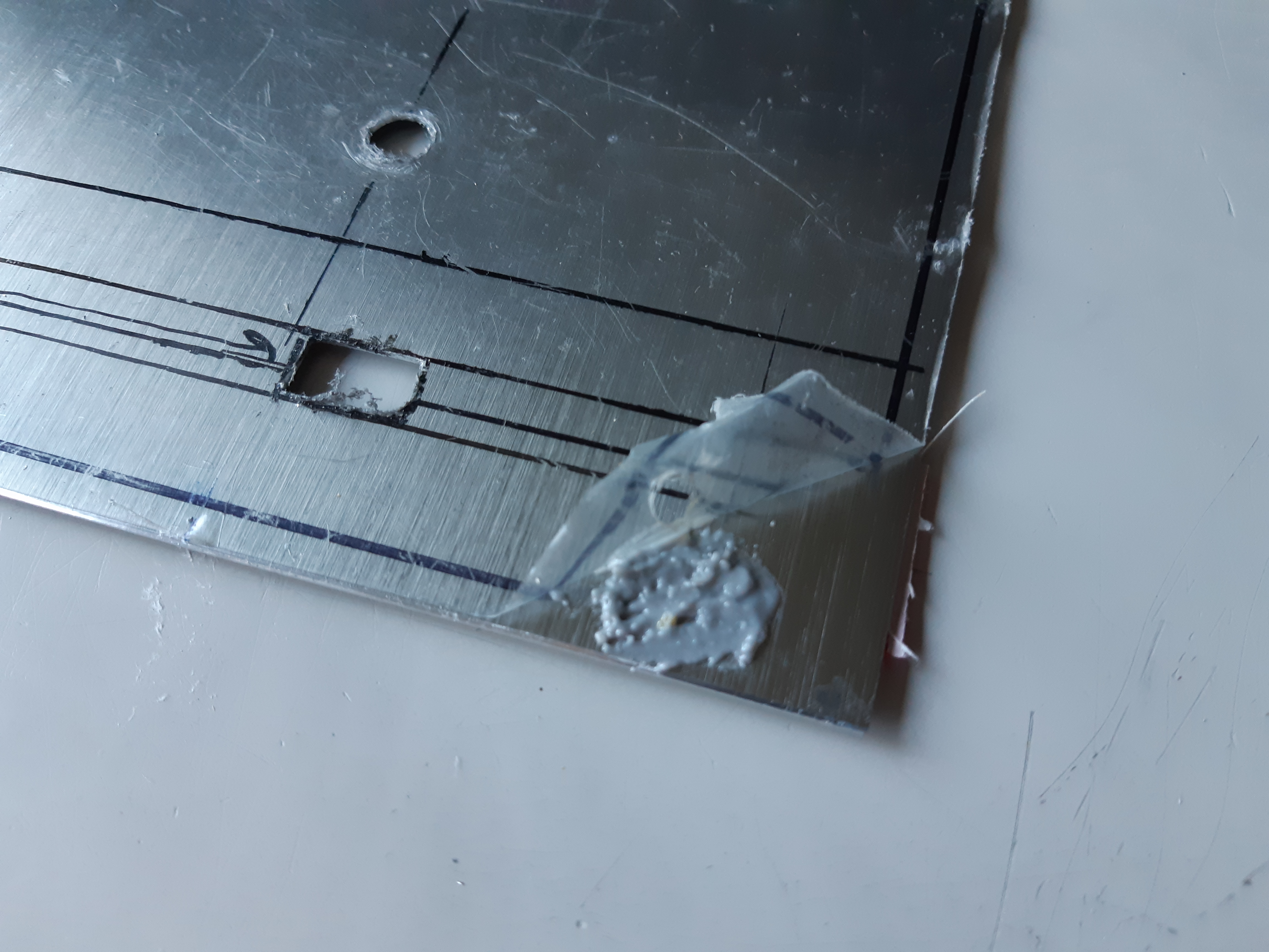
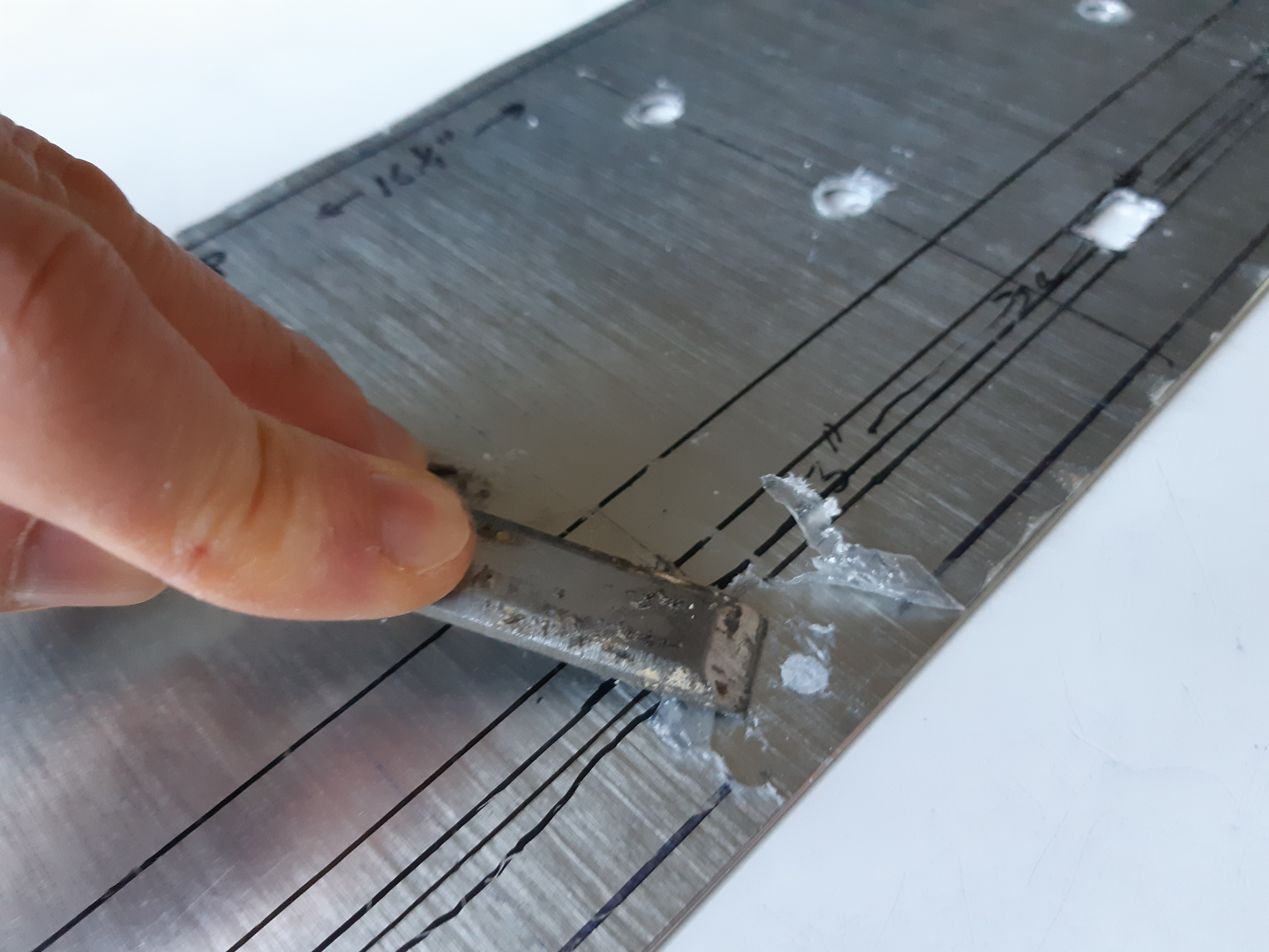
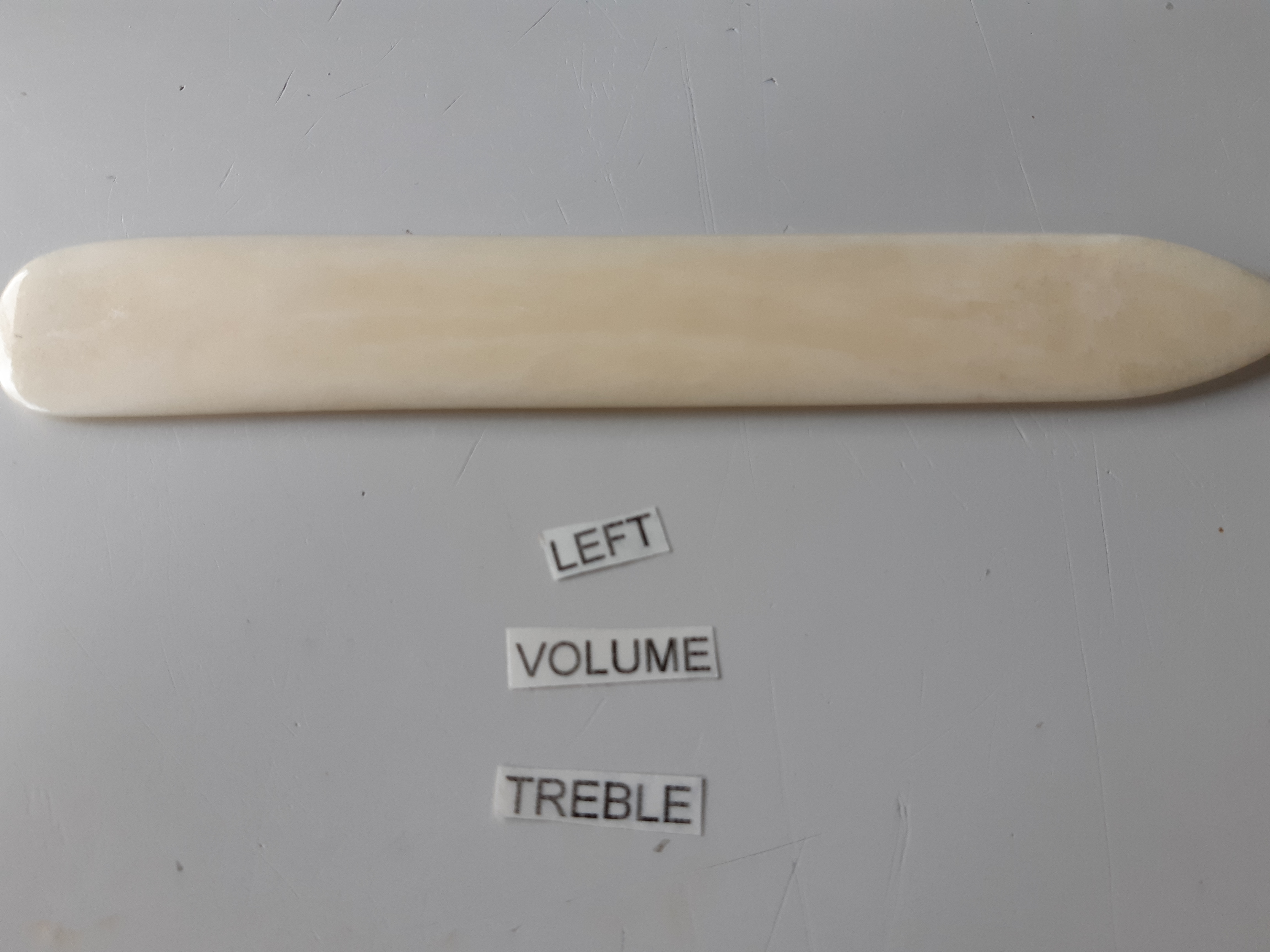
The surface was cleaned first with steel wool, then with rubbing alcohol (fig. 24), and a piece of cardboard was placed over the back of the hole (fig. 25) and held in place with tape. The epoxy steel was prepared according to the directions and smeared into the holes using a Popsicle stick (fig. 26), and then flattened (fig. 27). Excess was then removed with a scraper, allowed to dry and sanded with very fine sandpaper.
Assembling the Preamp Module
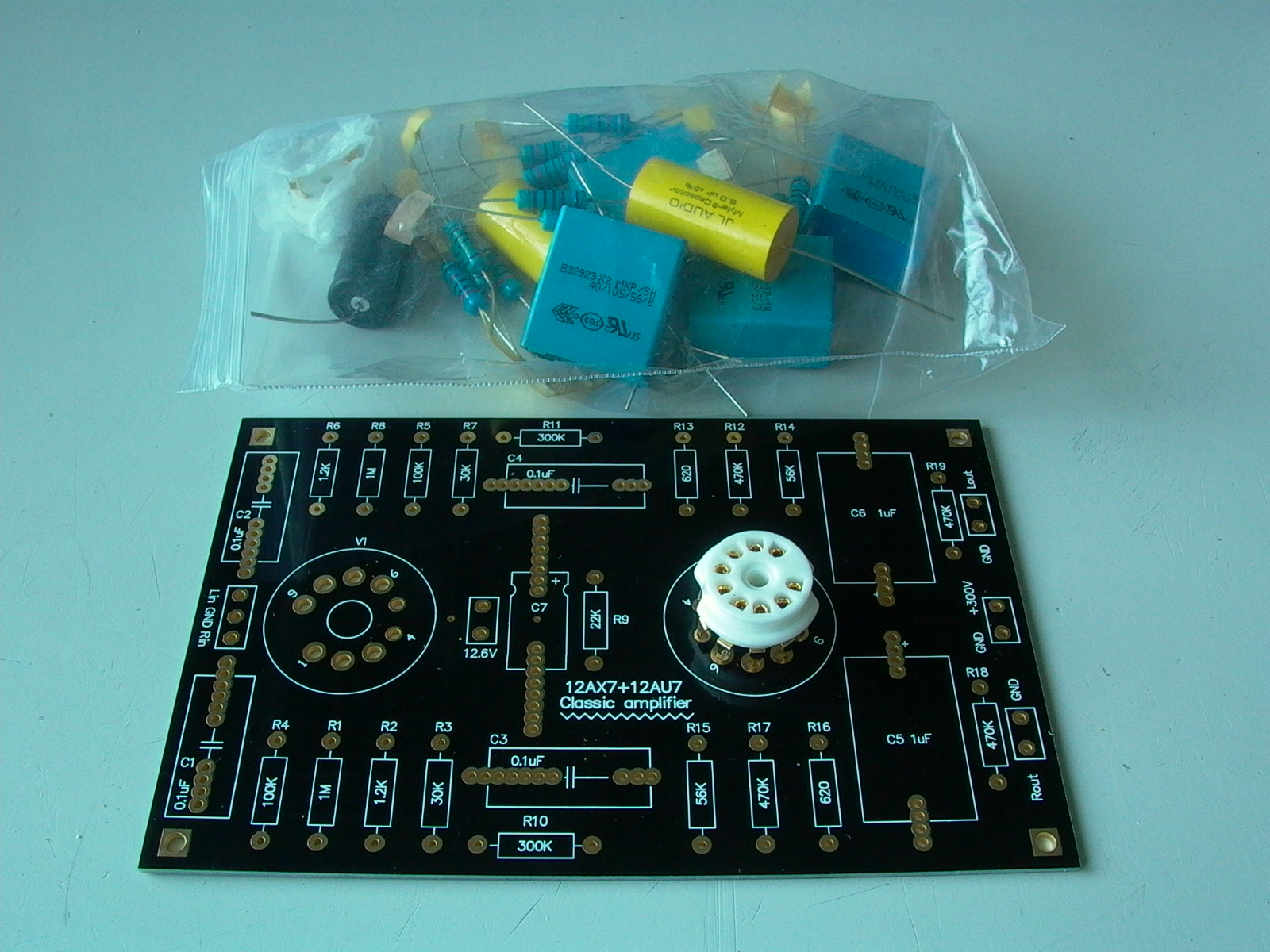
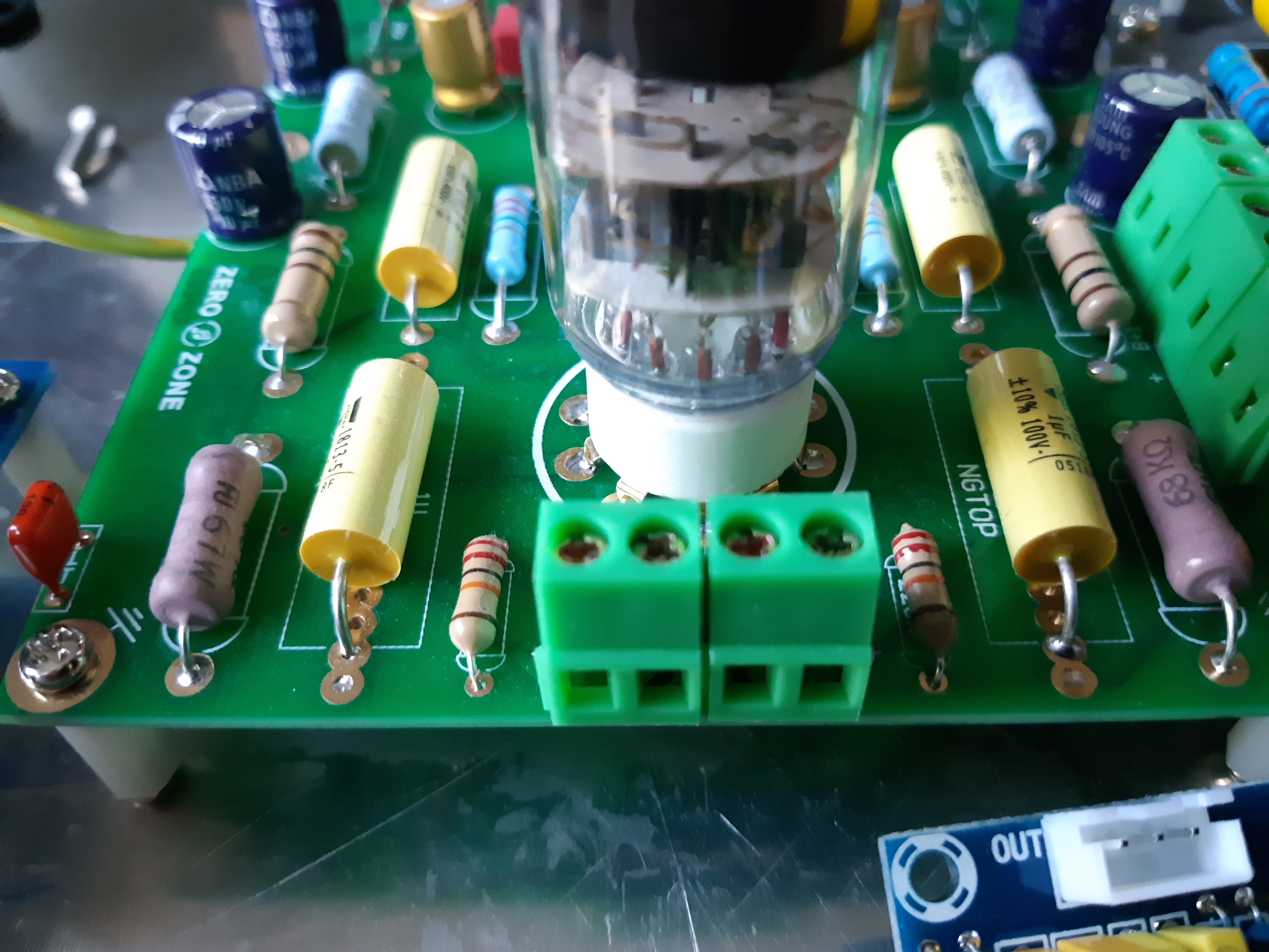
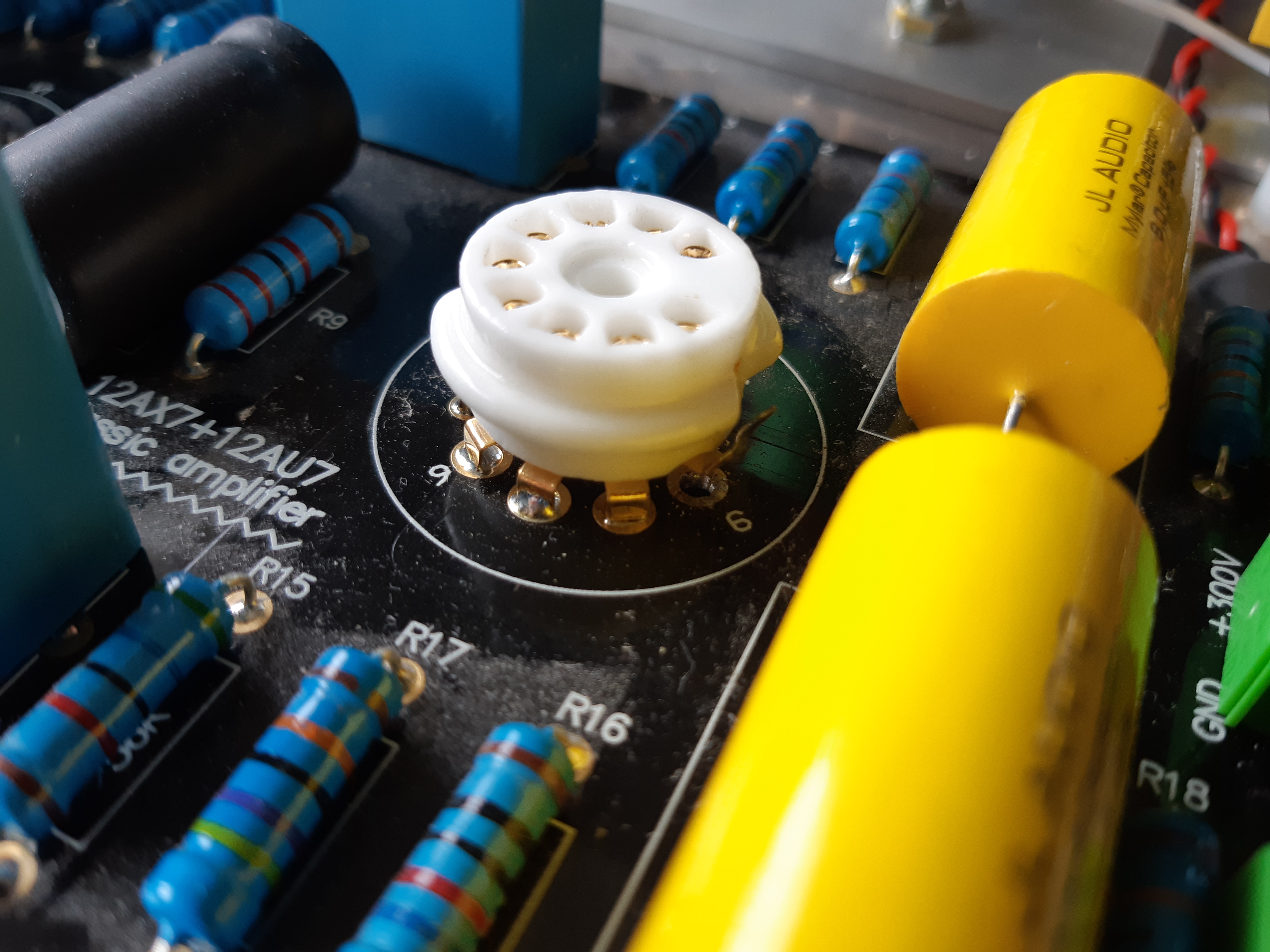
After a few weeks, my preamp kit arrived in the mail. It was rather strange that the seller did not provide instructions, and thus I had to refer to the seller’s image of the finished kit on eBay in order to assemble the module. As this is a kit, there is not much to write about. I have included a circuit diagram for your reference (fig. 29). The module is stereo but the circuit diagram shows only one channel as the other is identical and would be redundant. Tubes (not included) used for this module are 12AX7 and 12AU7 types, both of which are dual triode tubes. It requires an anode (plate) voltage of 300 volts DC and 12.6 volts for the filaments/heaters. According to the seller, the circuit topology is a copy of a classic design. This module is perhaps the most important component in the project as the preamp determines the overall quality of the sound.
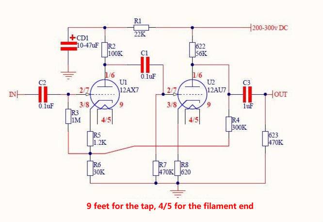
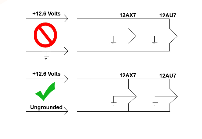
CAUTION: The center tap (pin 9) of both tubes are grounded to negative. If using 12.6 volts DC, make sure one side is not grounded to the same ground as that of the filament center taps or you risk burning out one of the heaters and/or melting the cathode (figure 30 – click for larger view)!
The Power Amp Module
The next kit to arrive in the mail was the power amplifier module (fig. 31 – image provided by seller). Because each circuit board has only one channel, I purchase two for stereo.
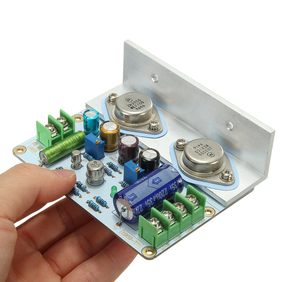
Known as the “JLH 1969”, the circuit uses a classic open-source all-transistor design by John Linsley Hood of England in 1969 (fig. 32). Each module uses four bipolar transistors. The main output transistors work together in push-pull Class A (constant “on”) mode and is capable of producing 10 to 15 watts per channel; as a Class A design, the amp is free of cross over distortion (a common problem with Class B and improperly biased Class AB push-pull amps). The JLH 1969 was said to be the best transistor design for hi-fi audio and is about as close as one can get in sound quality to that of a tube amp; as an open source design, I do not know why it is not used more often.
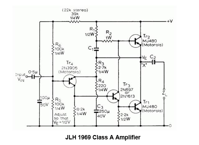
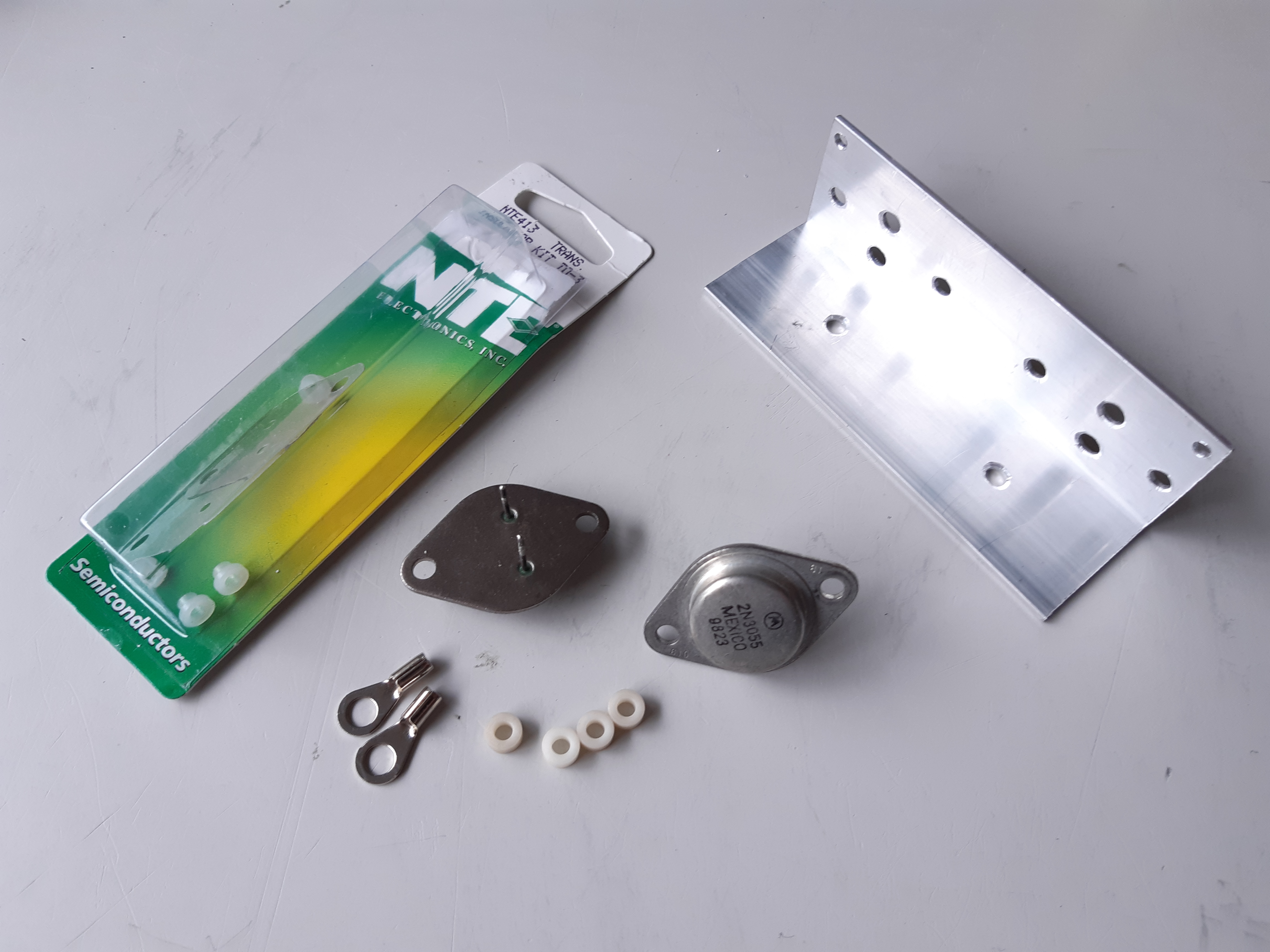
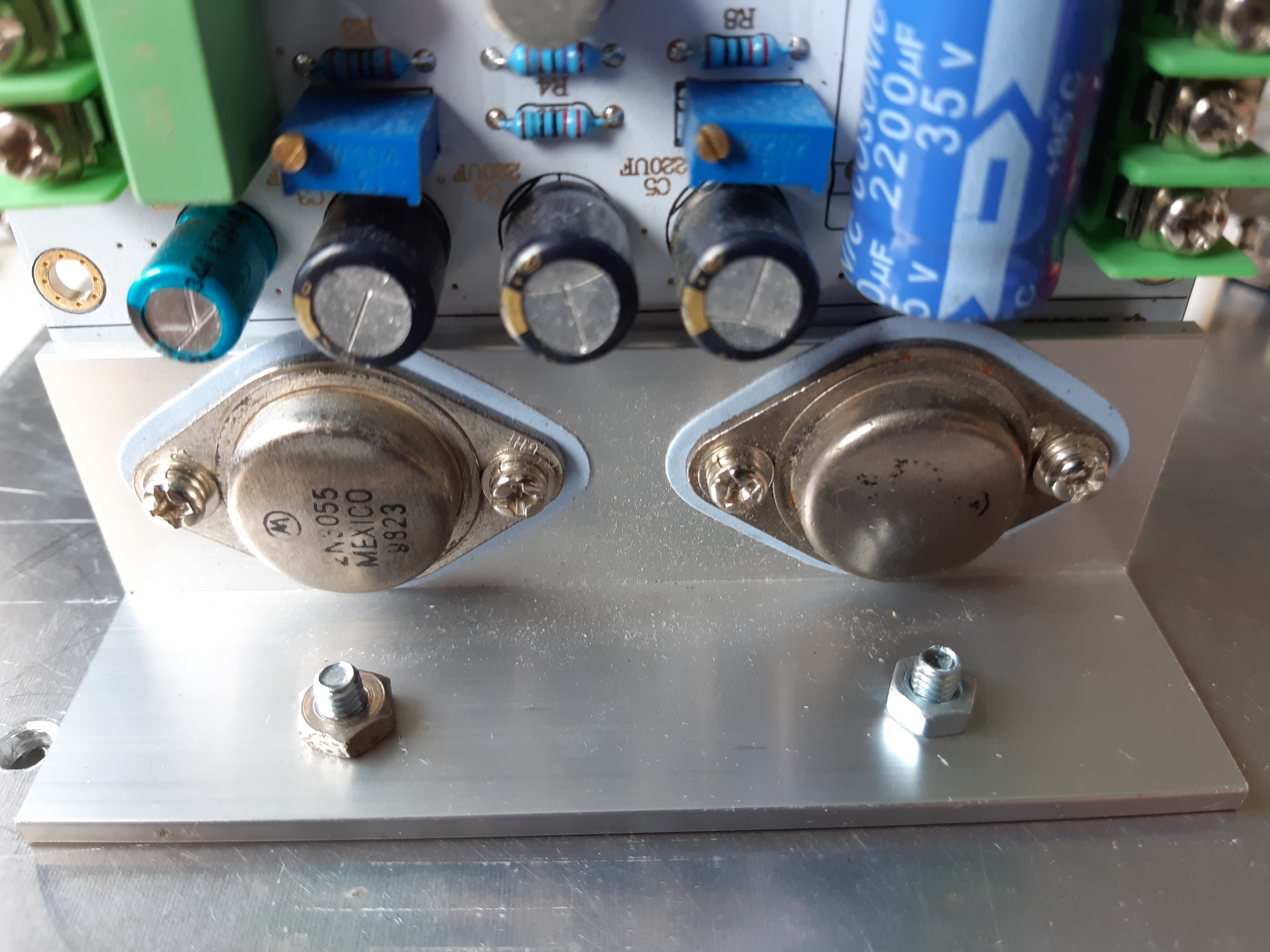
While the kit uses the original circuit topology, the transistors supplied are different. The first transistor (TR4 in the diagram) is a 2N2907, followed by a 2N1711 (TR3) and a pair of 2N3055 power transistors (TR2 and TR1).
I built the kit according to the sellers images (as with the preamp, instruction were not provided) but with two modifications. Instead of soldering the 2N1711 driver stage transistor (TR3) directly to the board, I soldered a transistor socket in its place. Transistor sockets offer a few advantages over directly soldering transistors into the board: transistors will not get damaged by the heat of the soldering iron (though rare, it can happen), it allows one to swap transistors around in selecting a type for best sound, and in the event of a problem, it simplifies trouble shooting and replacement.
Another important modification is that I plugged-in a 2N3866 VHF/UHF RF transistor into the socket (TR3 position – driver stage) instead of the 2N1711 supplied. The 2N3866, as an RF transistor, is commonly used in 2-way radios and video signal amplifiers, and is the workhorse of the 2-meter (144-148 MHz) and 70 cm (440-450 MHz) amateur radio bands, capable of putting out more than 1 watt. Though rarely (if ever) used in audio applications, I have found that the 2N3866 is an excellent performer with a smooth warm sound when used in small signal (i.e. preamp and driver) stages. Another similar VHF RF transistor that works very well in audio with equally outstanding sound quality is the 2N4427. The 2N5109, though I have not tried it myself in audio applications, is another RF transistor one could use in the JLH module; it’s basically a 2N3866 on steroids, capable of amplifying up to 1.2 GHz (1200 MHz). As the 2N3866 is plugged into a transistor socket instead of being soldered directly to the board, I can swap around when I have some time later.
Because the JLH 1969 is a Class A design, the main output transistors (2N3055) are constantly “on”, even when there is no input signal or when silent. Thus, the output transistors can become very hot and therefore, must be mounted to a heatsink. The angled bracket onto which the power transistors are mounted are NOT heatsinks themselves but rather for mounting to a heatsink. As shown later on, the chassis of the unit will be used as the heatsink, resulting in the board standing upright.
CAUTION: the body of the output transistors is part of the collector while the heatsink may be grounded to negative (depending on what you use as the heatsink and how it’s installed). Dropping a metal object such as a coin or even a small scrap of wire on the transistors could cause a short, blowing out the transistors!
The Phono Stage Preamp
Shortly after completion of the JLH 1969 amplifier module, the phono preamp kit module arrived in the mail. As with the previous kits, the phono module did not come with instruction but parts were complete (minus the tubes) and component values were labelled on the board.
This kit is a stereo phono preamp and uses three tubes (3 x 12AX7). Its design incorporates a circuit for equalization following a standard set by the Recording Industry Association of America in the 1950’s and phono stages or preamps such is this module are simple called RIAA.
I do not have room for a vinyl record collection and since I rarely listen to my records, the RIAA unit will only serve as a space filler and/or spare tube holder in the amp. It will be hooked up but the tube filaments will just remain disconnected.
As with the other modules, it was easy to assemble but since I currently have no plans to use it anytime soon (although not ruled out), I do not have much to comment. Should I wish to activate the RIAA phono unit in the future, it’s just a matter of hooking up the 12.6 volt tube filament supply.
Building the Power Supply
The final active module was the power supply. Unlike the phono board, preamp, and power amps – all of which were built from kits – the power supply was built from scratch.
When I first started this project, I had initially planned to build a solar powered transistor-tube hybrid amp for use in a camper. However, this idea turned out to be impractical for a number of reasons; storage batteries would be drained rather quickly (less than an hour for a 7.5AH lead acid gel cell) at twilight, a built-in inverter module to convert low voltage DC from solar panels and batteries to high voltage AC would be noisy, and other issues making the idea more difficult than it actually sounds. I had then changed my mind and decided to make it a home desktop unit; the power supply would have to use 117 volts AC at 60Hz (I’m in Canada) and convert it to 12.6 volts DC for the tube filaments and transistor power amp modules, and 250-350 volts DC for the tube modules.
Looking at my supply of spare parts, I found a multi-winding transformer with two separate 117 volt (110-120 volts) primary windings intended for dual voltage (117 and 234 volt), a 110 volt secondary, and a 50 volt center tapped (25-0-25) winding. 110 volts is not enough voltage for the tube preamp modules (they require around 300 volts), while 50 or even 25 volts is too high for the tube filaments and the JLH transistor amp modules; but with a voltage doubler for high voltage and a voltage regulator to bring down the low voltage, this transformer is perfect.
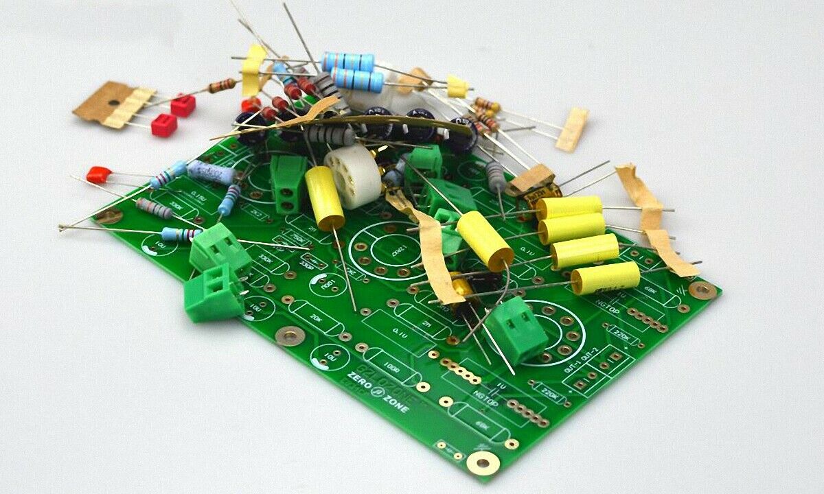
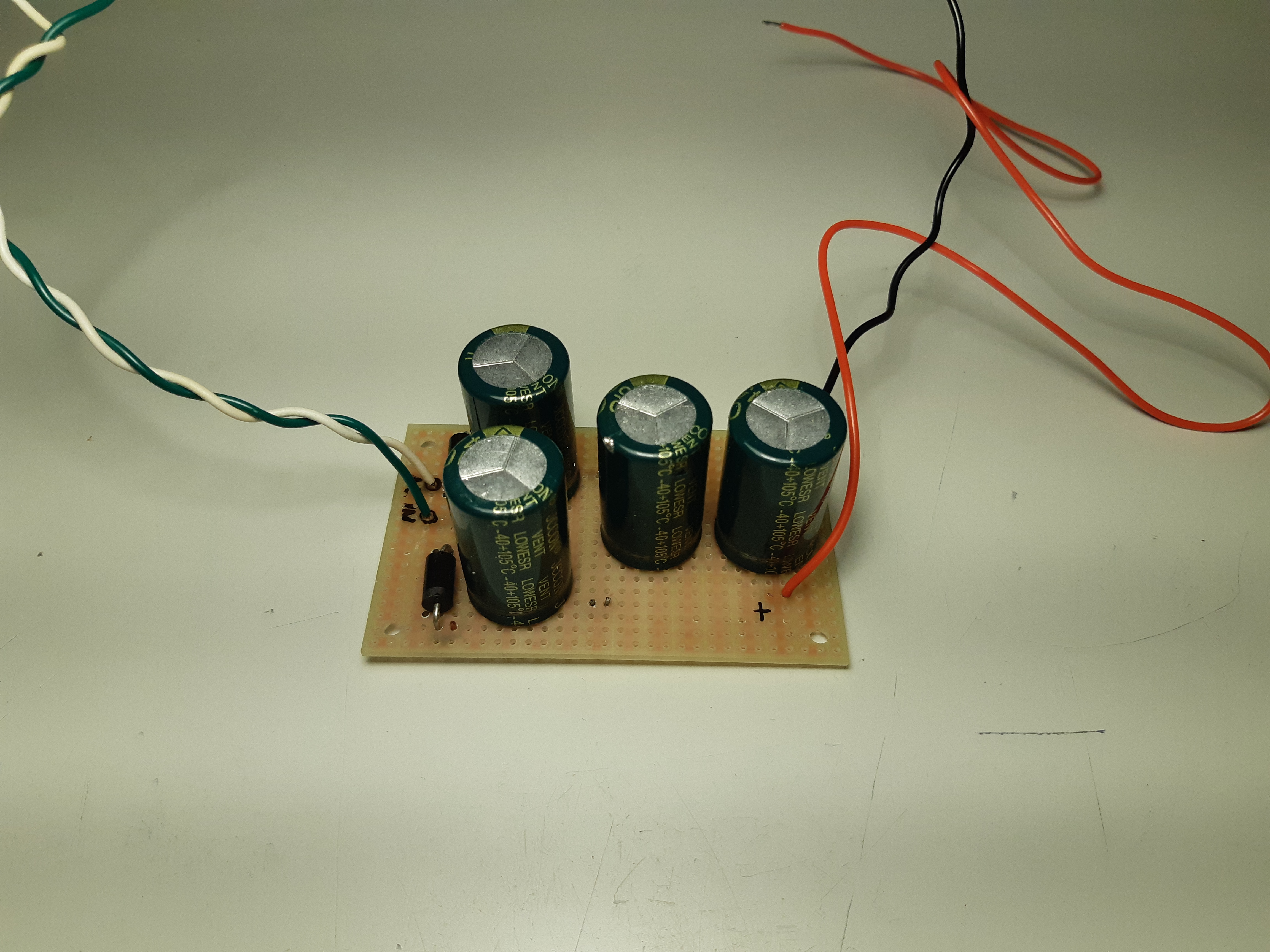
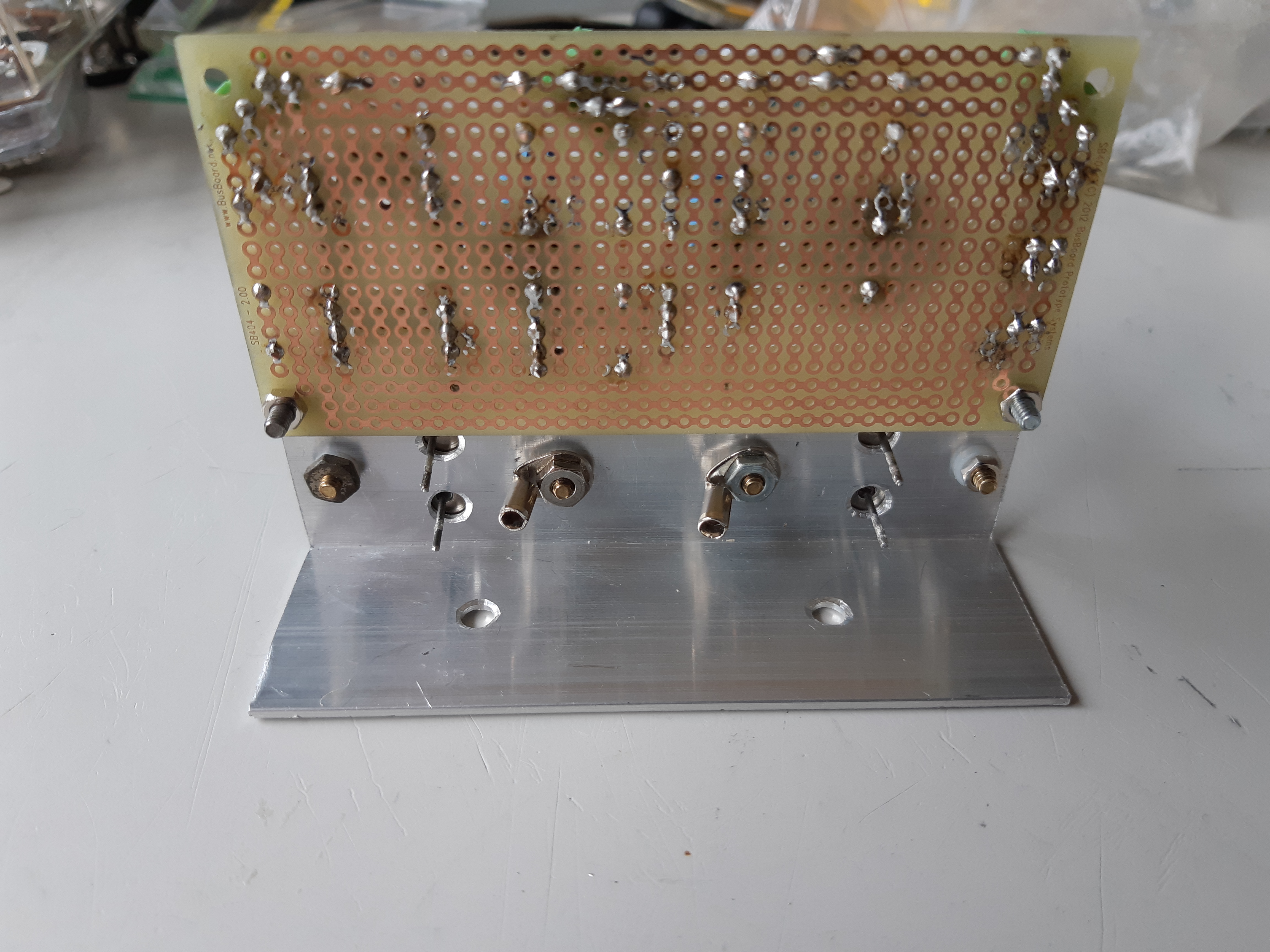
The high voltage doubler and low voltage section with the voltage regulator were built on separate boards. I used prototype boards (perf boards) onto which I assembled the components. In building the voltage multiplier module (a full wave mulitplier), the first step was to decide how to layout components (fig. 35). When I was satisfied with the arrangement, component leads were left intact and bent to form the path (fig. 36) and the soldered together (fig. 37).
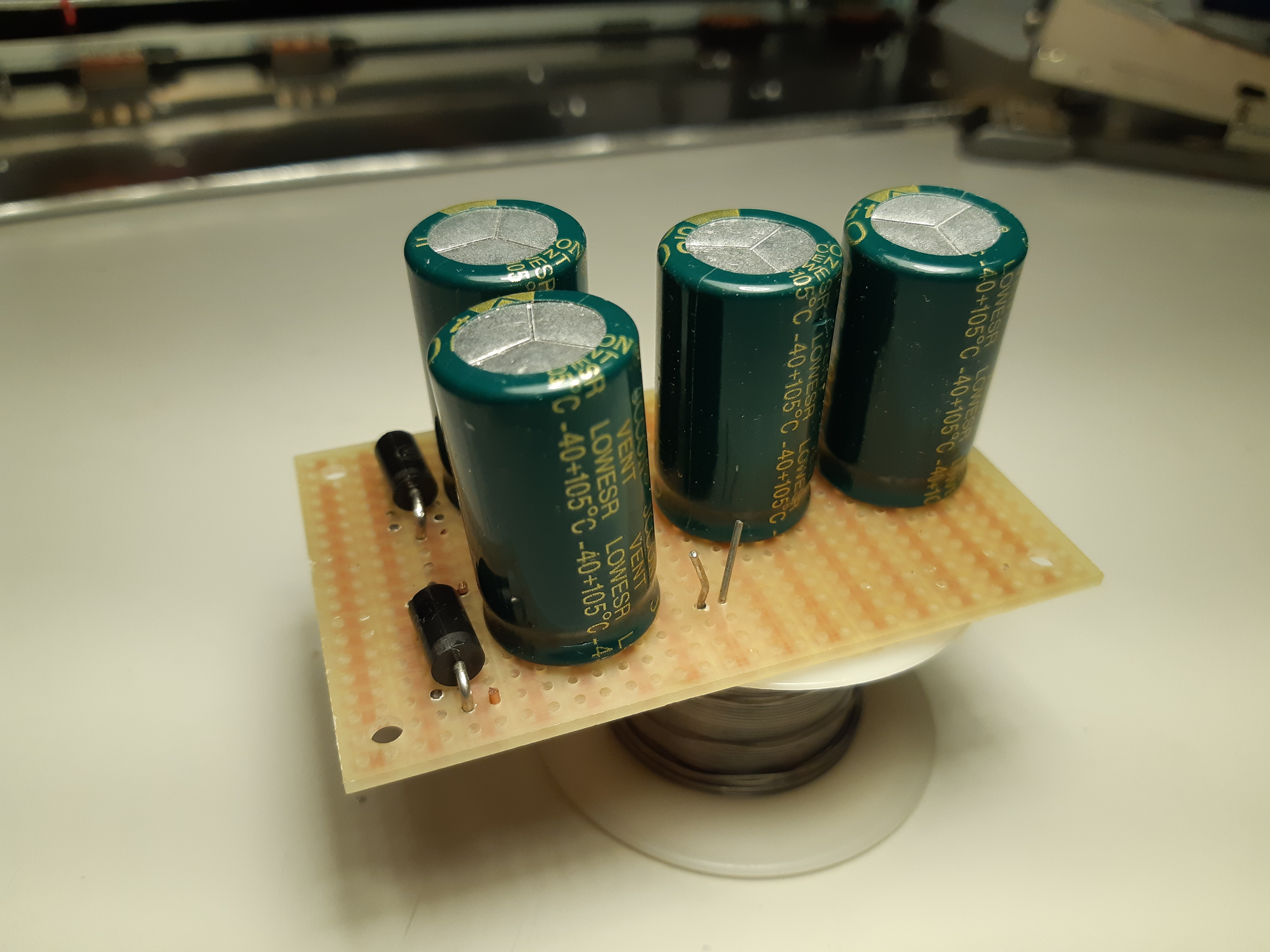
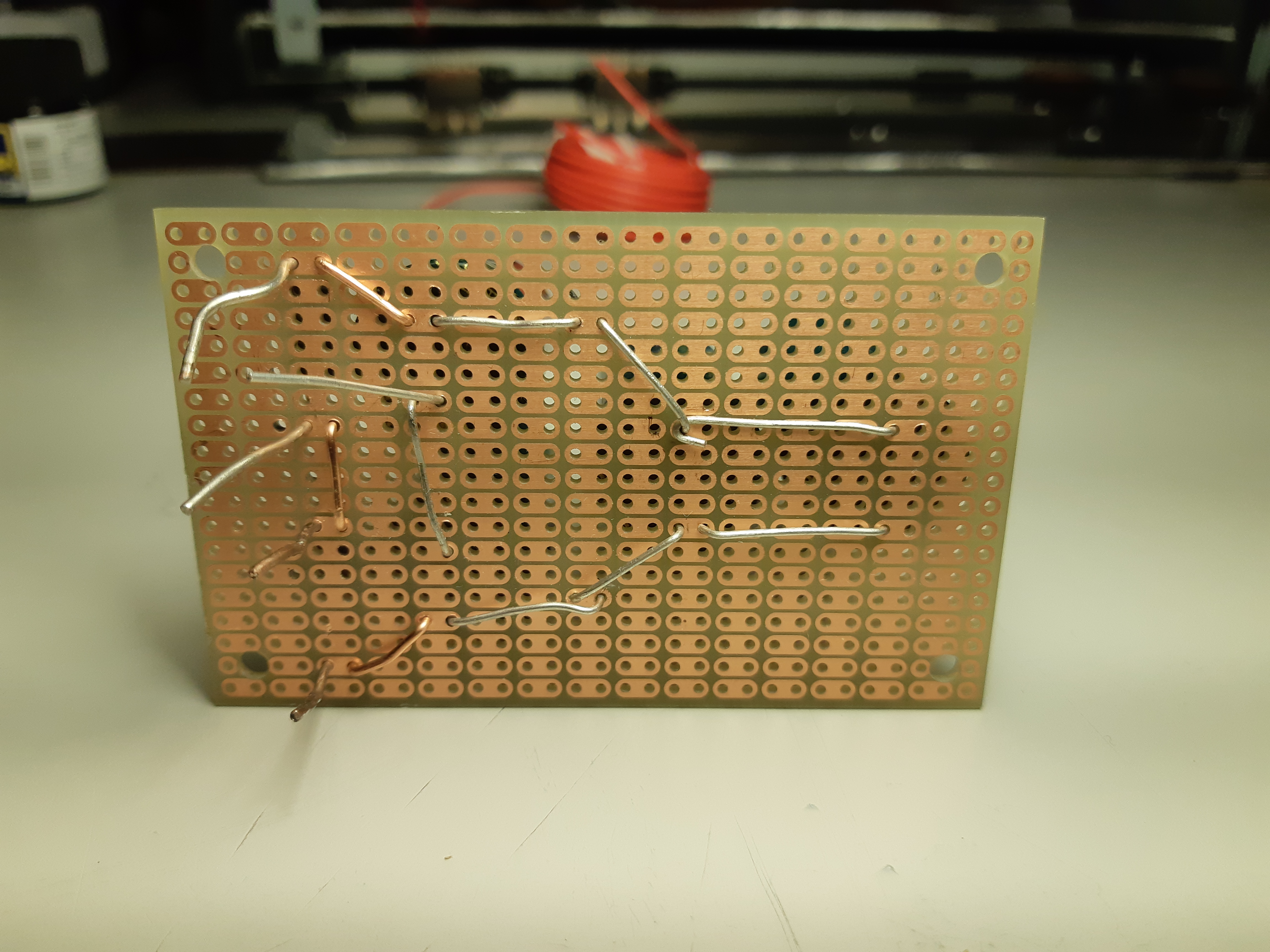
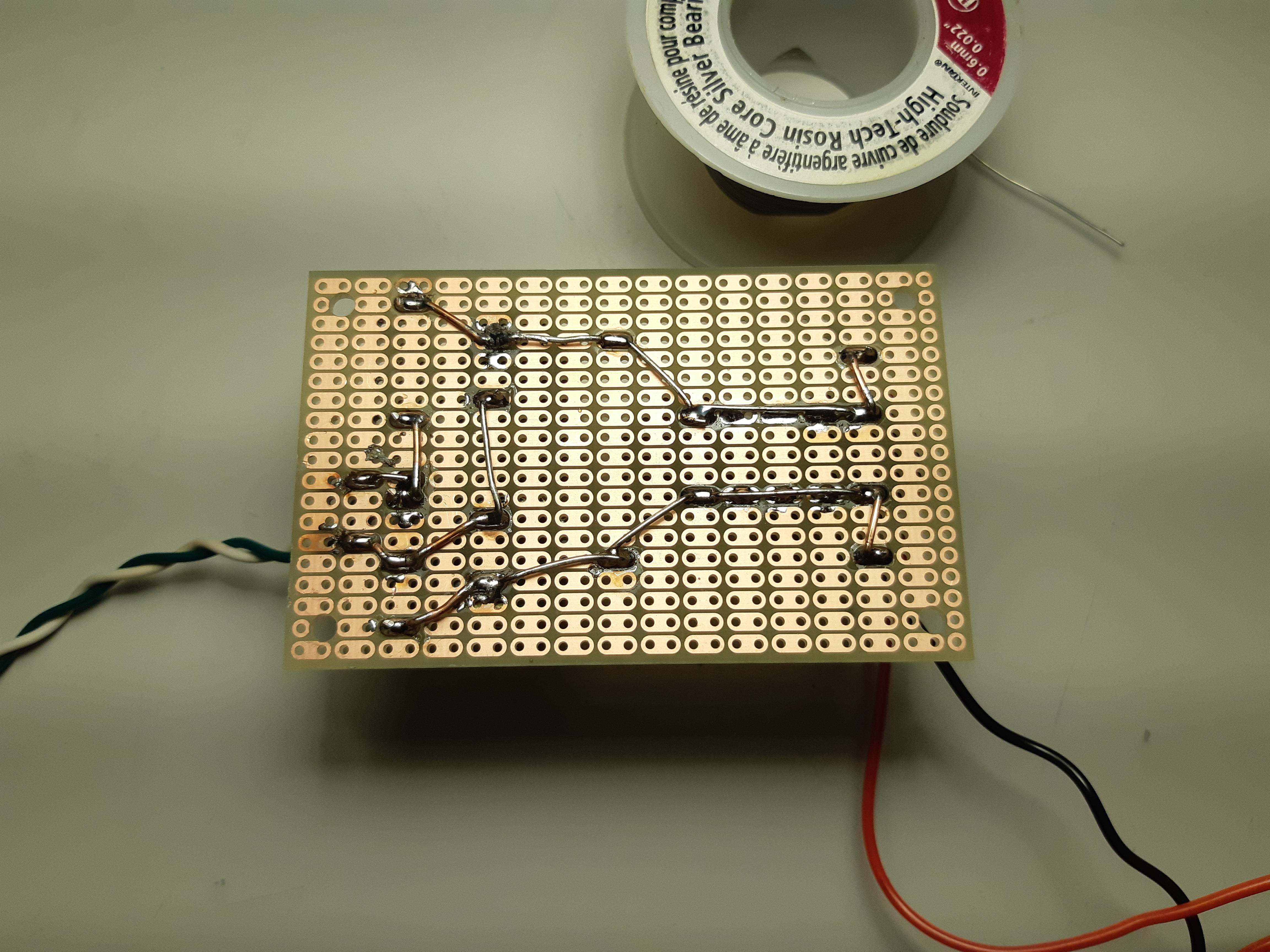
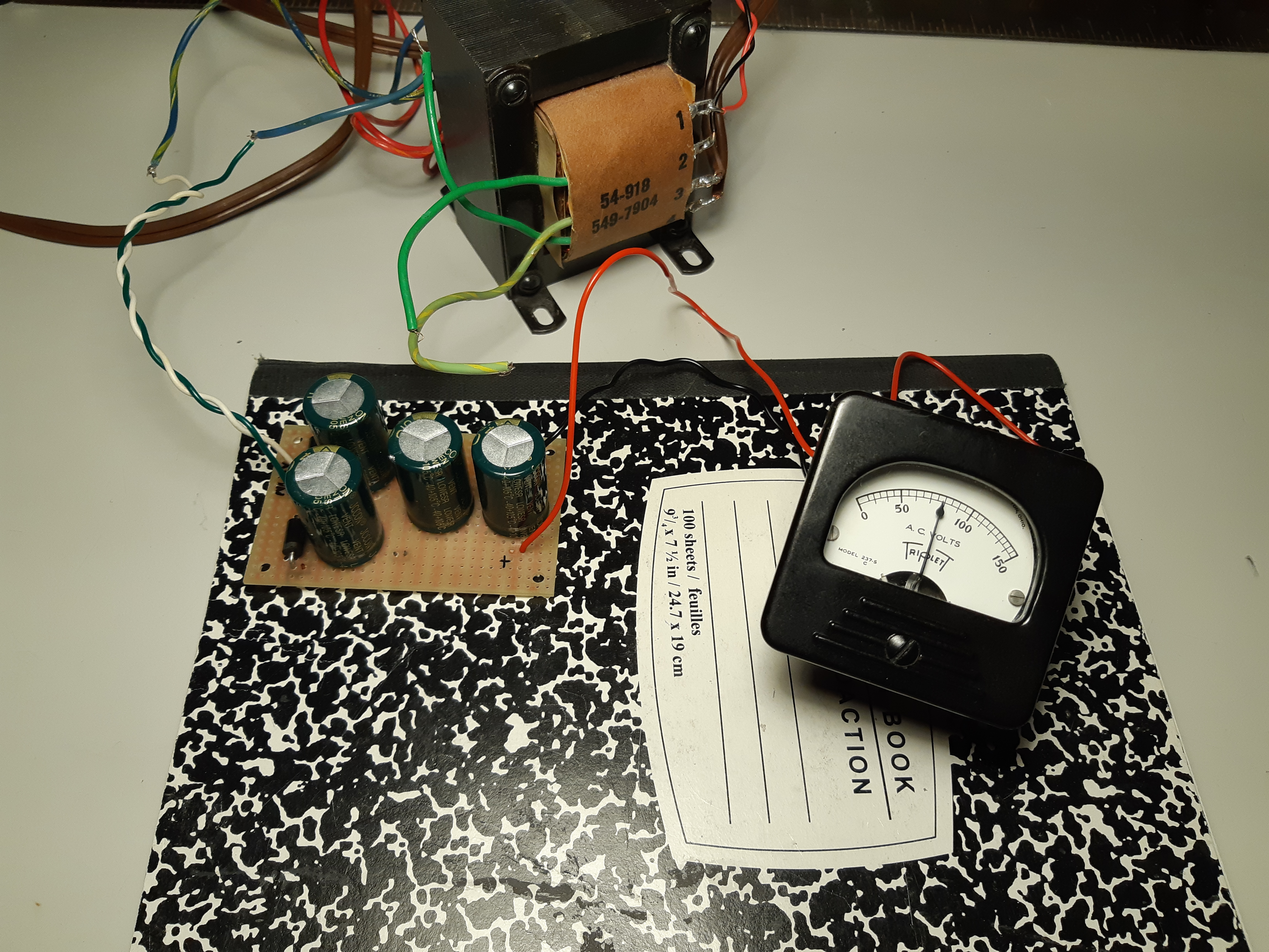
As soon as the voltage muliplier board was finished (fig. 38), the board was tested. With a no-load voltage of 28 volts AC at the input, the circuit gave almost 80 volts of full wave DC (for sine wave, output volatge = input volatage x 2 x 1.41) (fig. 39).
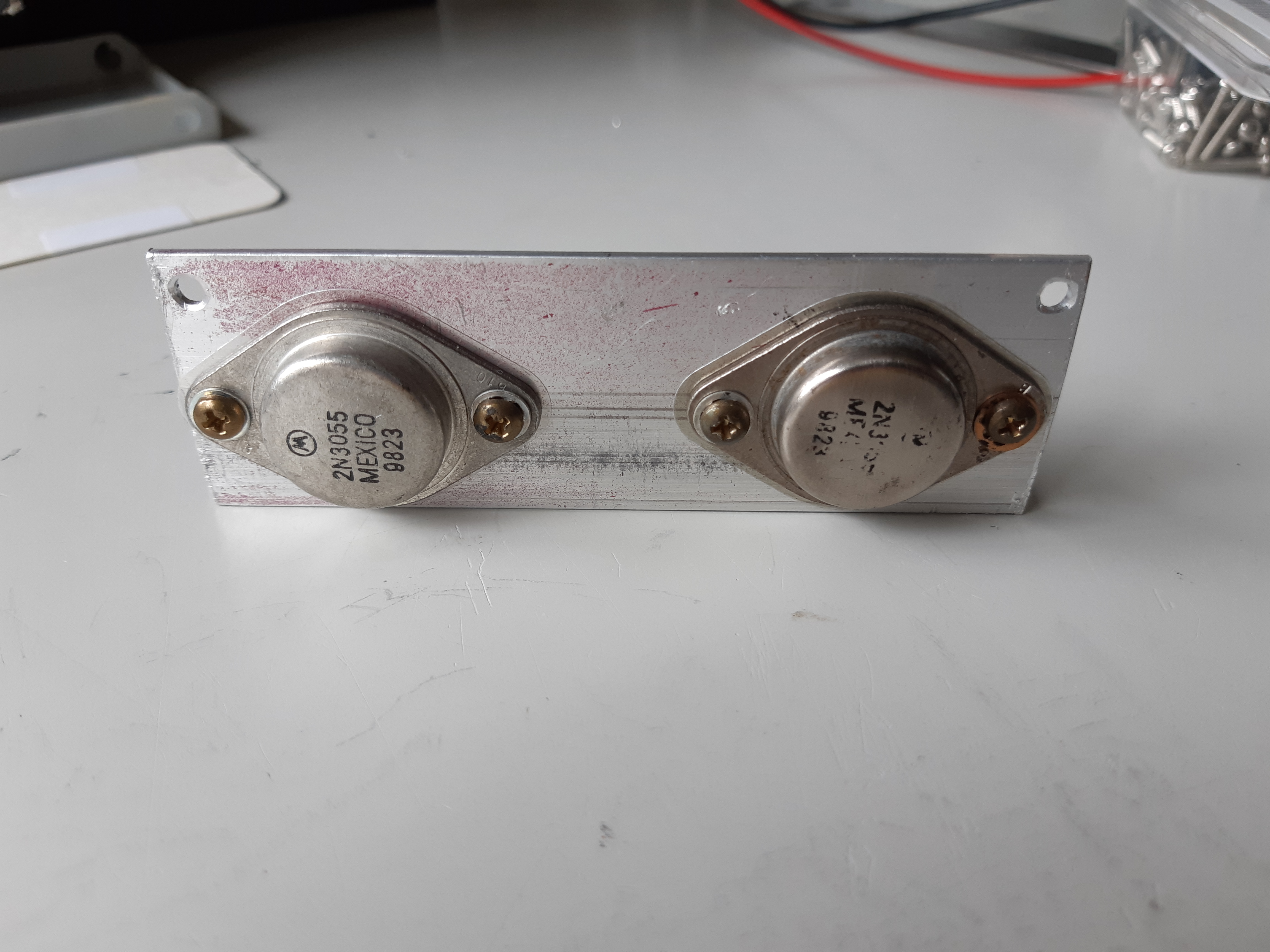
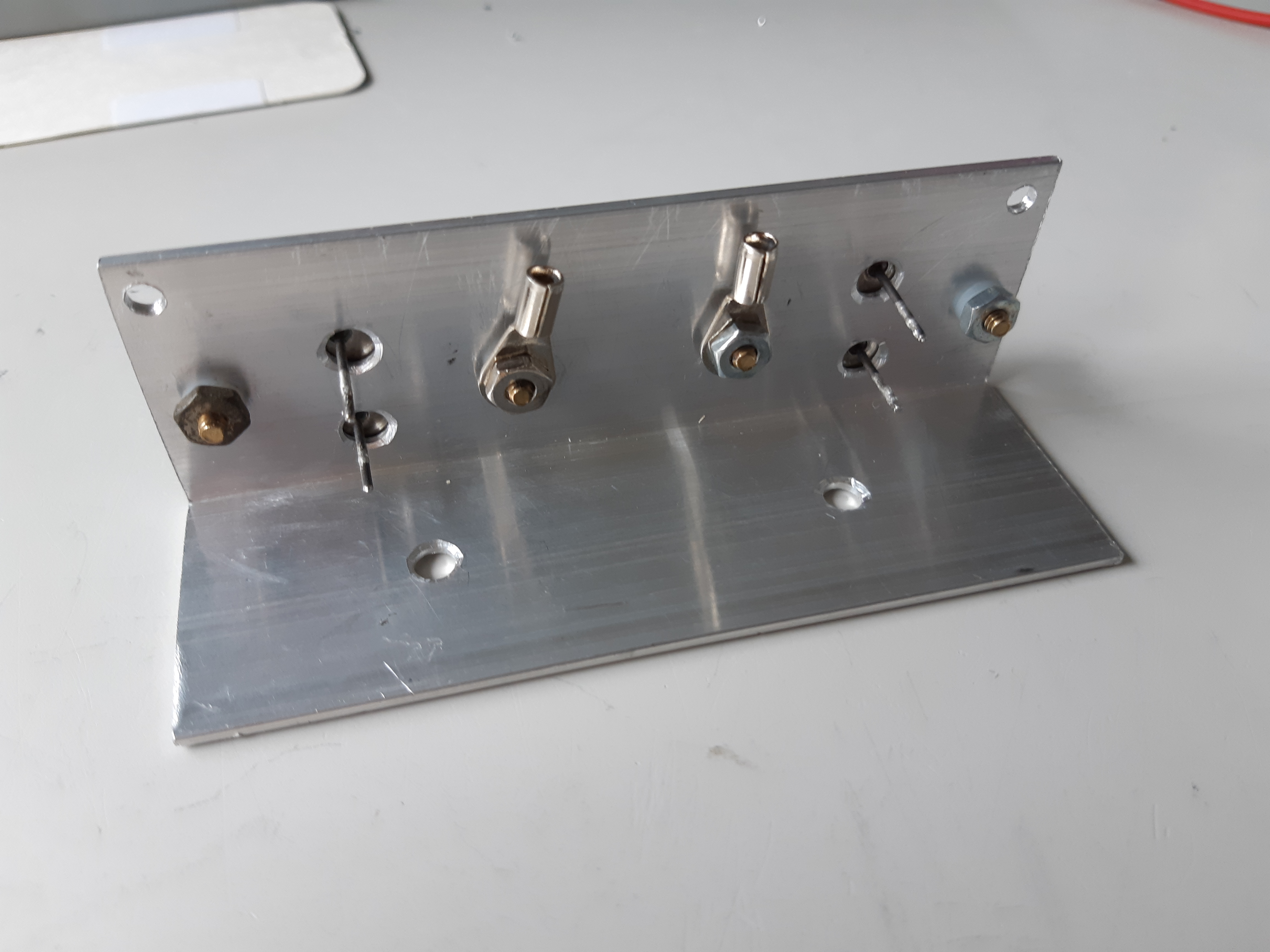
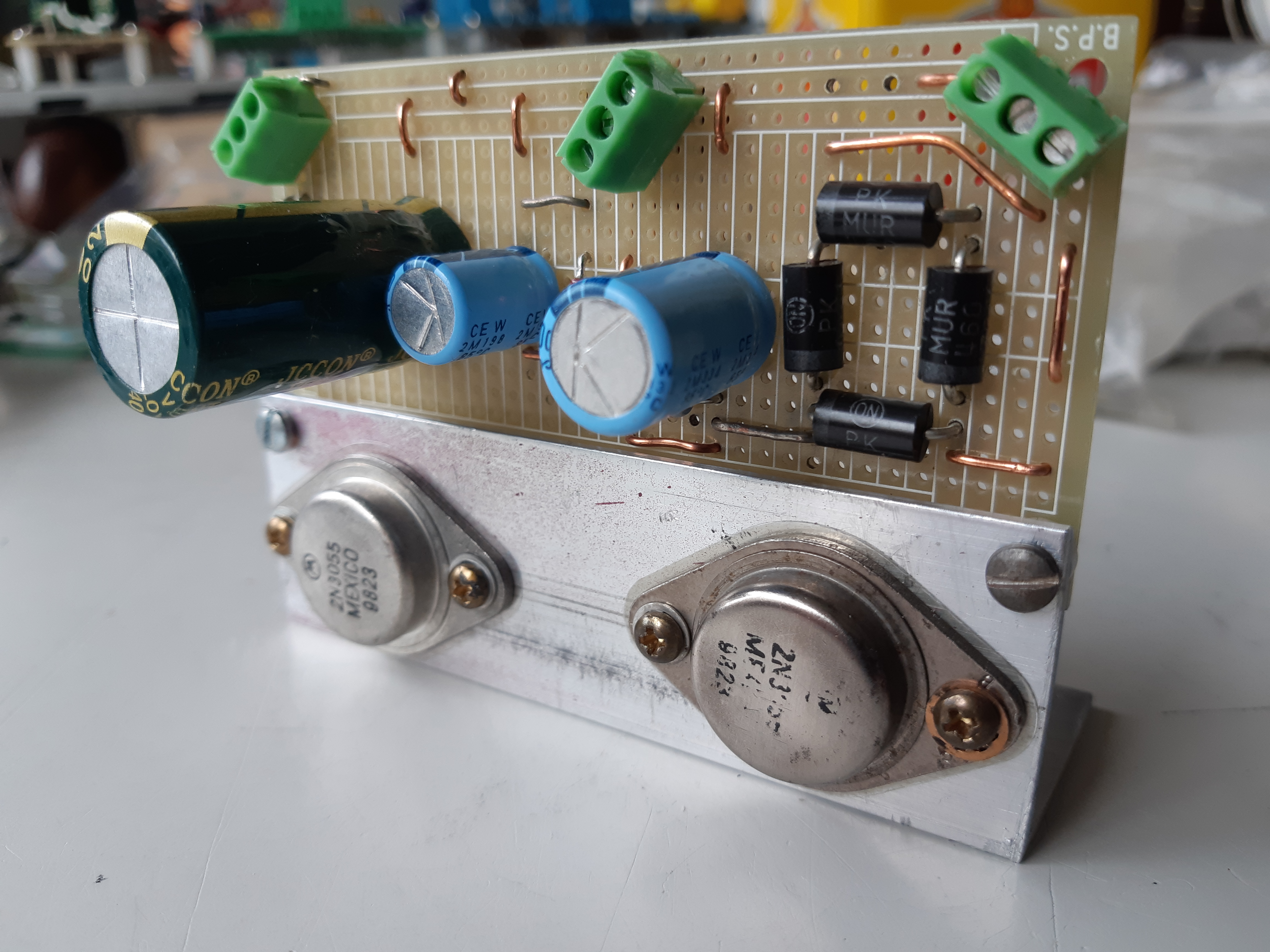
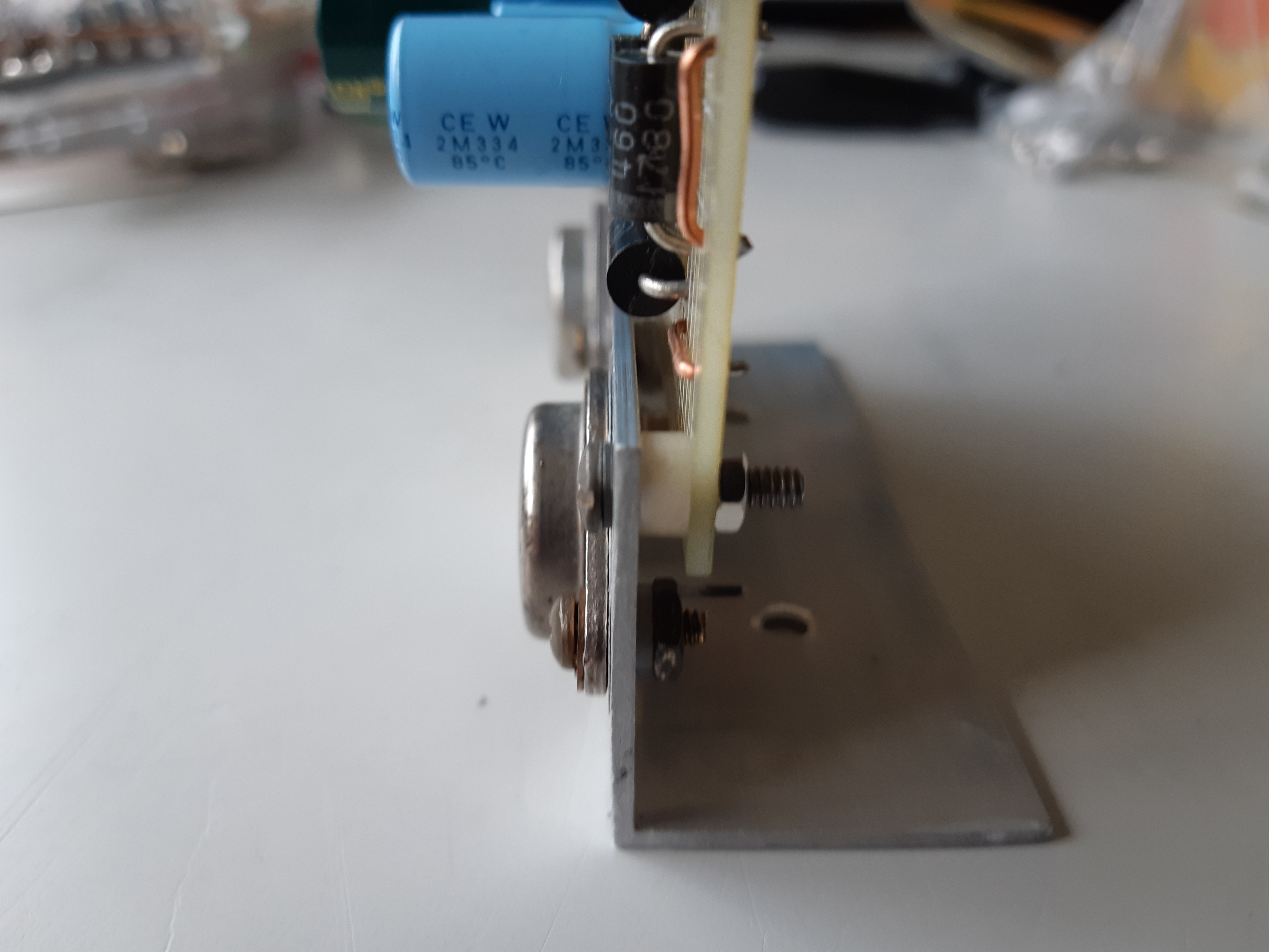
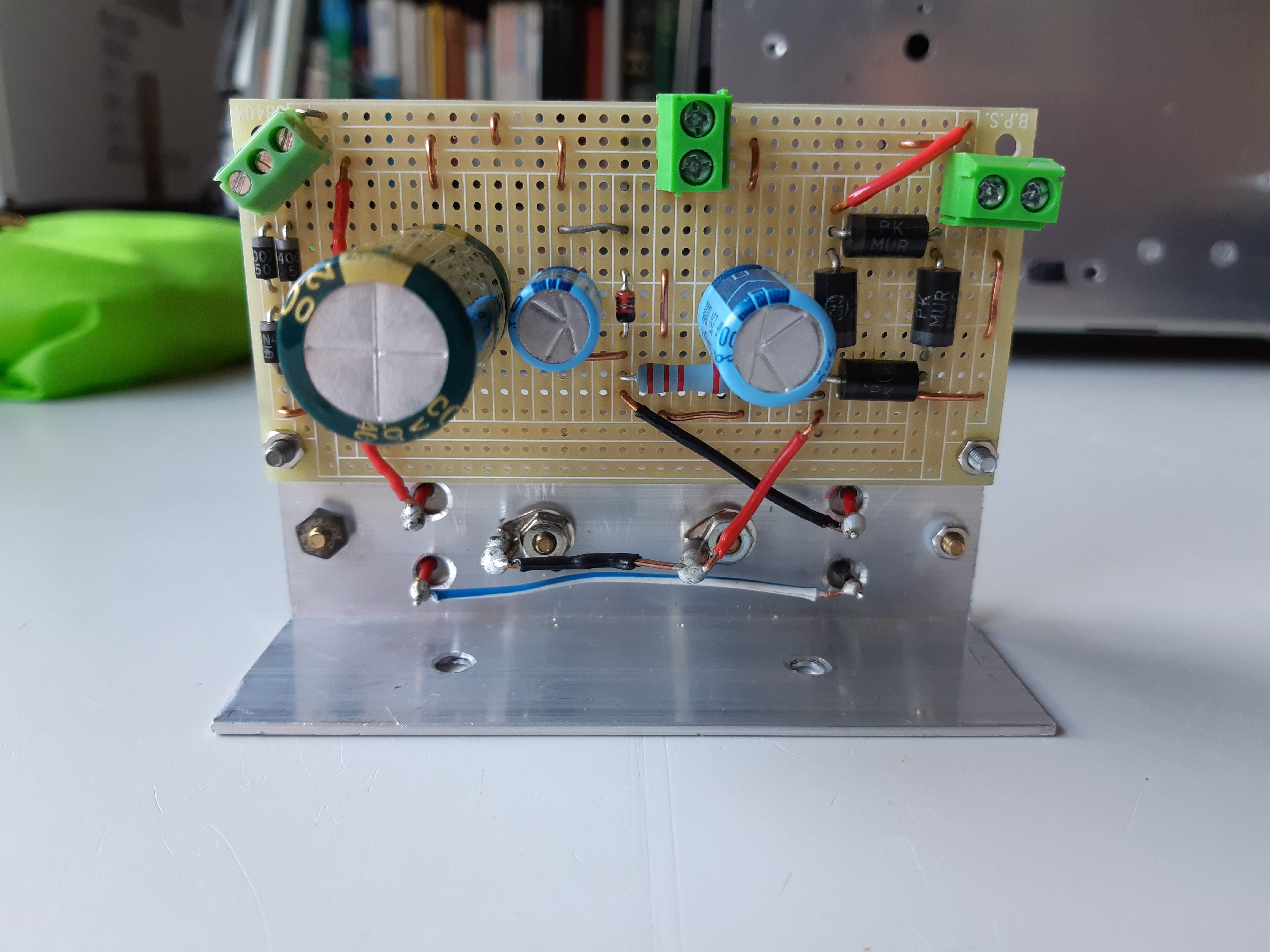
The low voltage section, which includes a full wave bridge rectifier and 2-transistor pass regular, was built on a separate board. The 2N3055 transistors were mounted to a piece of angle bracket and like the JLH 1969 amplifier, it will be heatsinked to the chassis and mounted upright (figures 40 to 46).
Of the two 117 volt primary windings, only one will be used for the AC mains supply. Since the other winding is not connected, it is a very useful source of isolated 117 volts and will be used for the power on indicator light and accessory power outlet at the back. The schematic diagram below maps out the entire power supply section (fig. 47 – click on image to view).
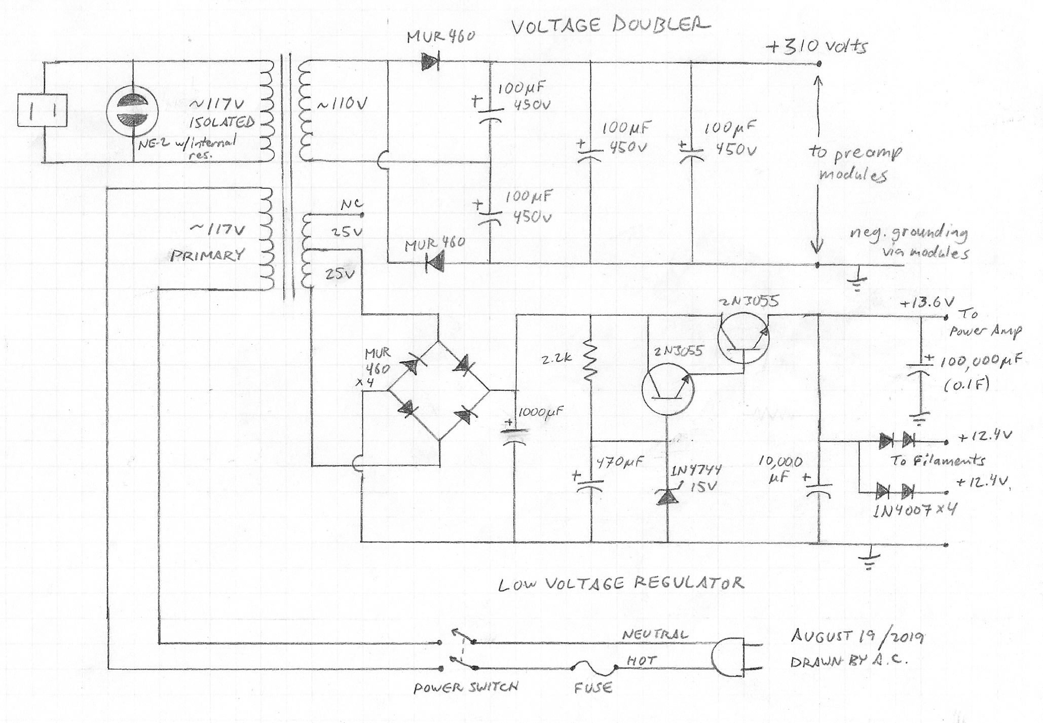
All rectifier diodes use were type MUR460 ultra fast recovery diodes rated to 600 volts at 4 amps. As these are suitable for use in modern heavy duty switch mode power supplies, I originally bought them for use with a 200kHz inverter when I was planning on using solar power.
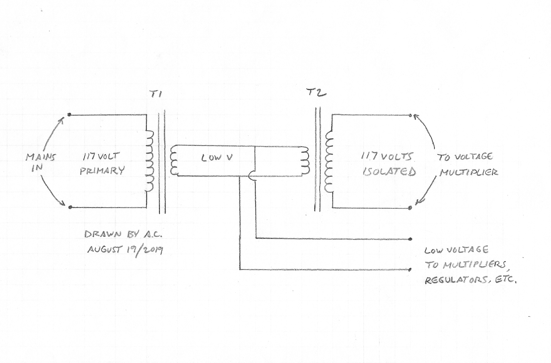
A new transformer with multiple windings for high and low voltages can be hard to find and when new ones are available, they are often expensive. One hack is to take two identical low voltage transformers (for example, 120 volts to 12.6 volt step down transformers which are cheap and plentiful) and wire the secondaries back-to-back, providing an isolated 117 volts and 12.6 volts, which can then be boosted with a multiplier or stepped down with a regulator (fig. 48 – click on image to view). An added bonus is that this set-up gives you double isolation from the electrical mains. Be sure to use the correct wattage (volt amp rating) or your transformers will blow-up!
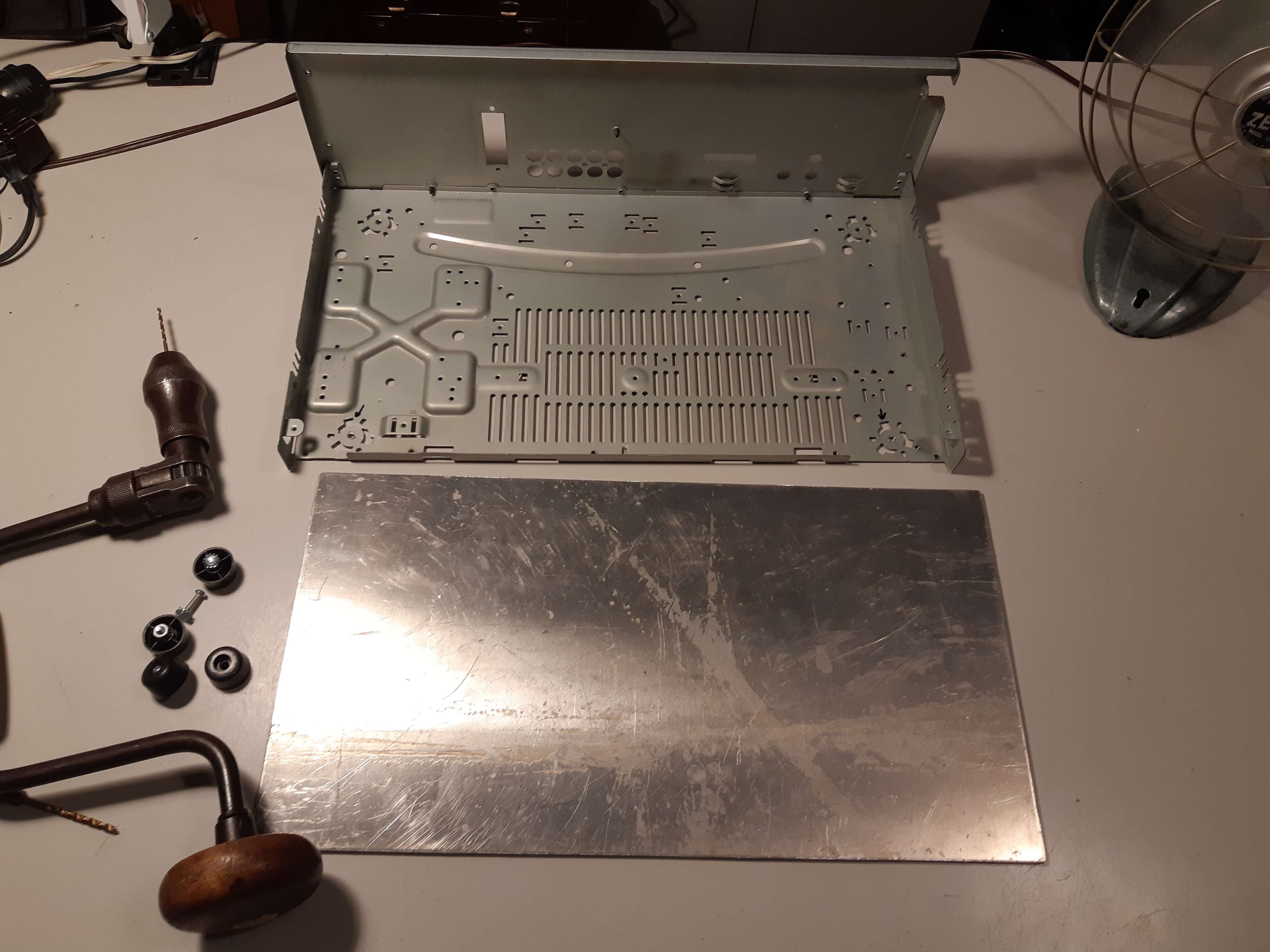
Building the Chassis
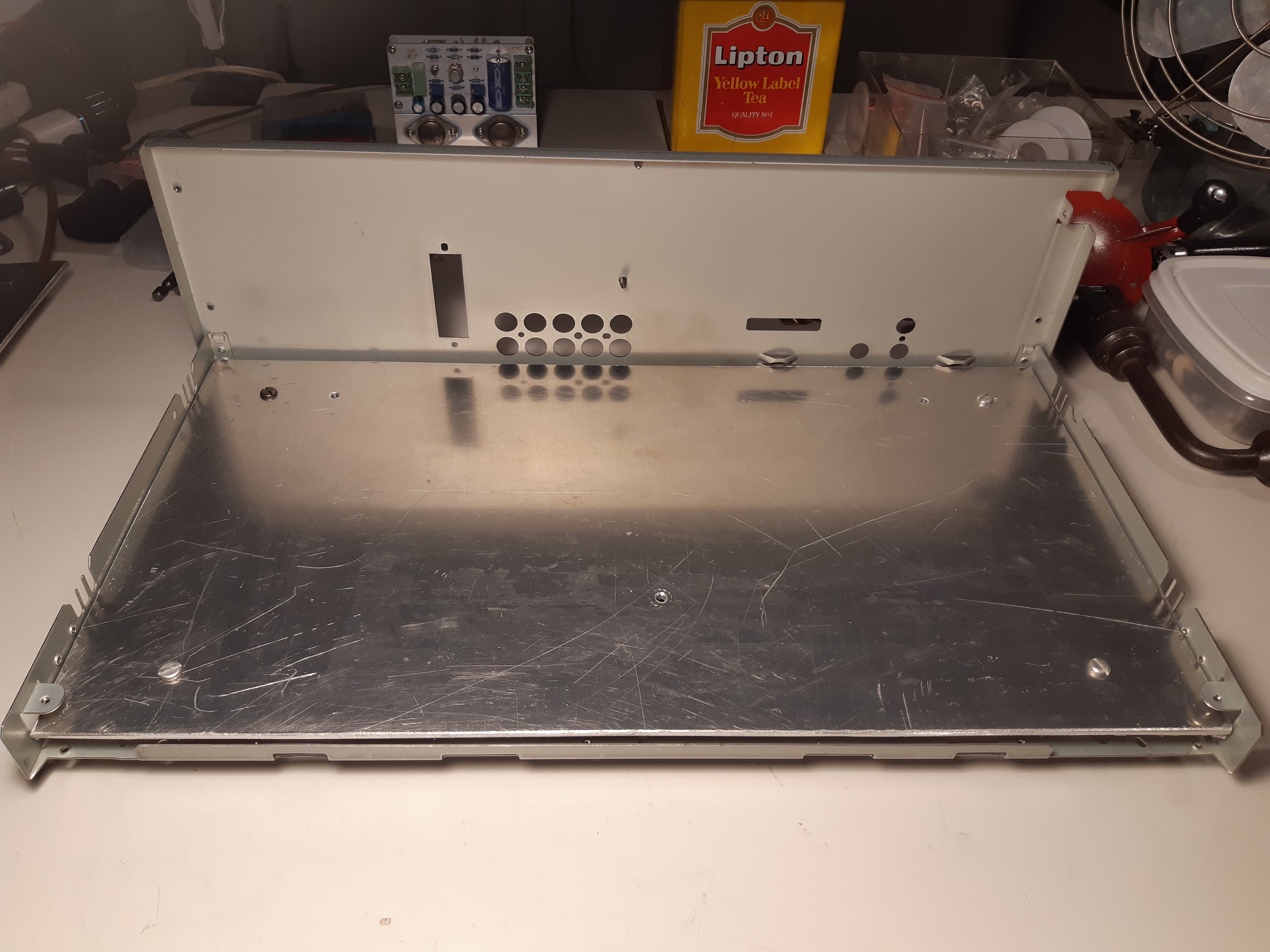
With all the modules ready, it was now time to build the chassis from the prepared shell of the gutted Pioneer CX-770s. Because the bottom piece of the case, in addition to being thin and flimsy, has a vent grille cut right into it, it may not support heavy components such as a transformer nor would I be able to install the modules anywhere I wanted them positioned. Thus, I had to cover and reinforce the bottom with a sheet of 1/8″ thick sheet of aluminum (fig. 49). This piece was more that just the floor of the chassis onto which modules will be bolted but it would also serve as a heat sink for the power transistors of the JLH 1969 amp and voltage regulator modules.
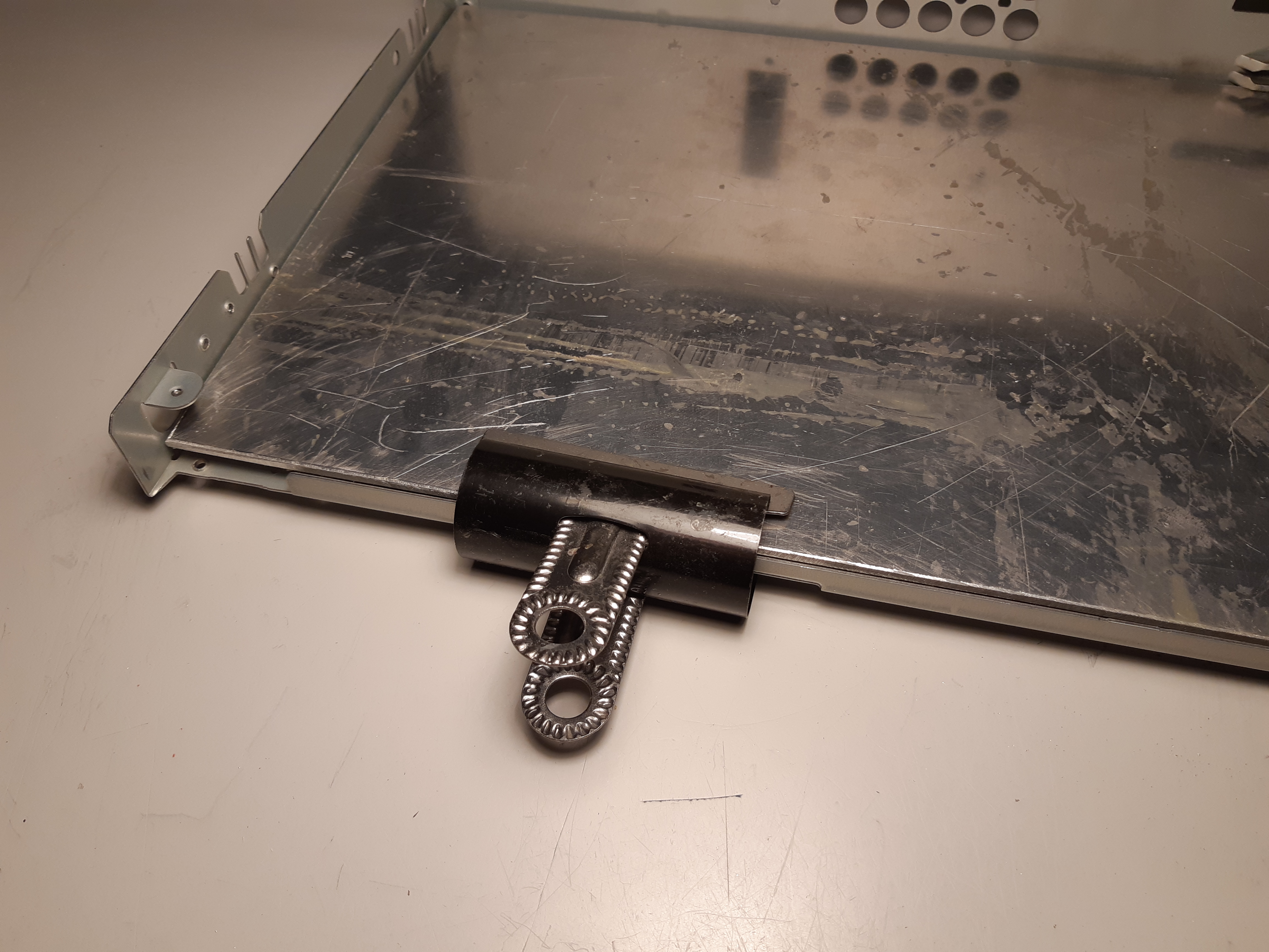
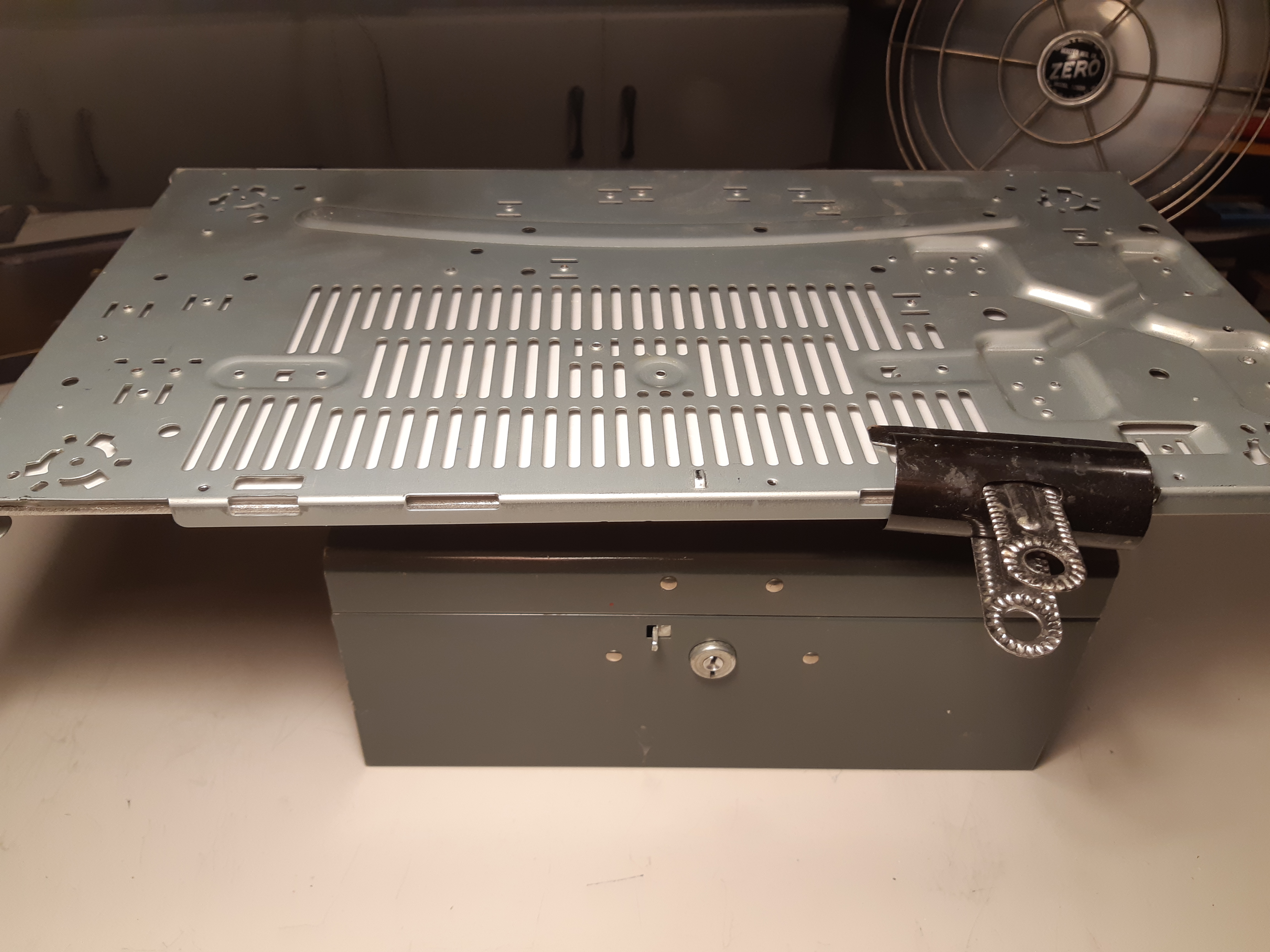
The bottom piece was then held in place with spring clips for drilling (figures 50 and 51).
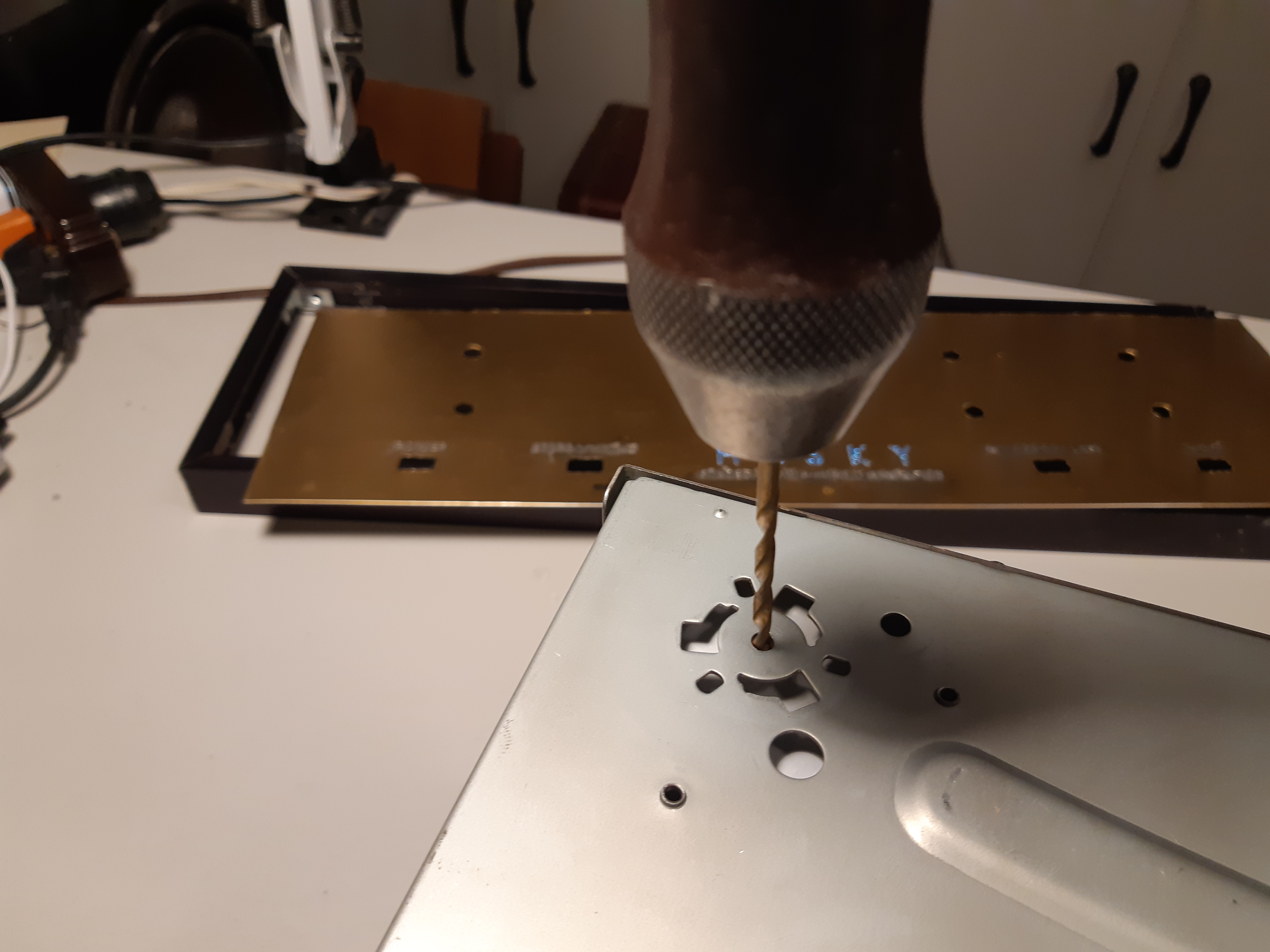
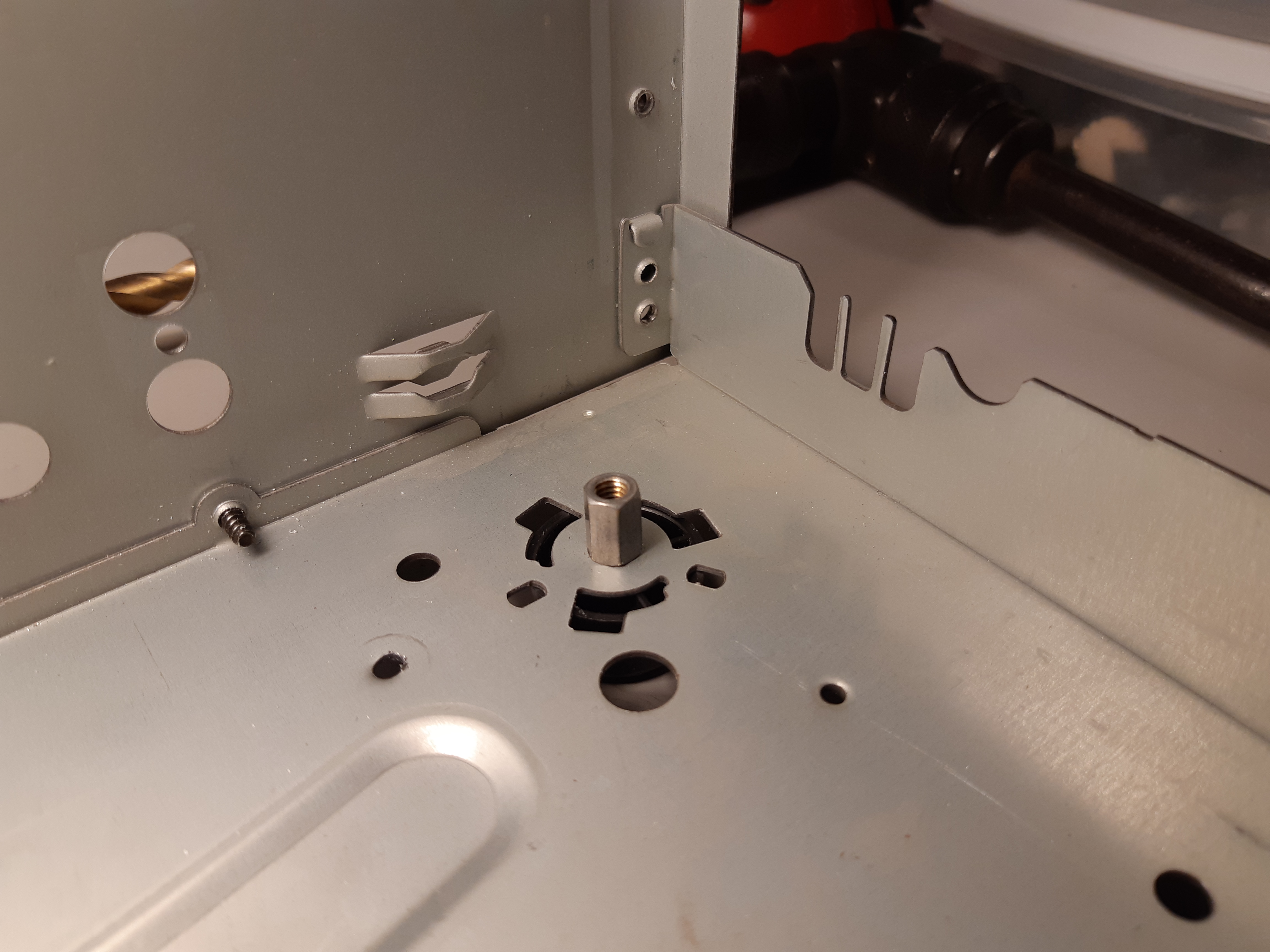
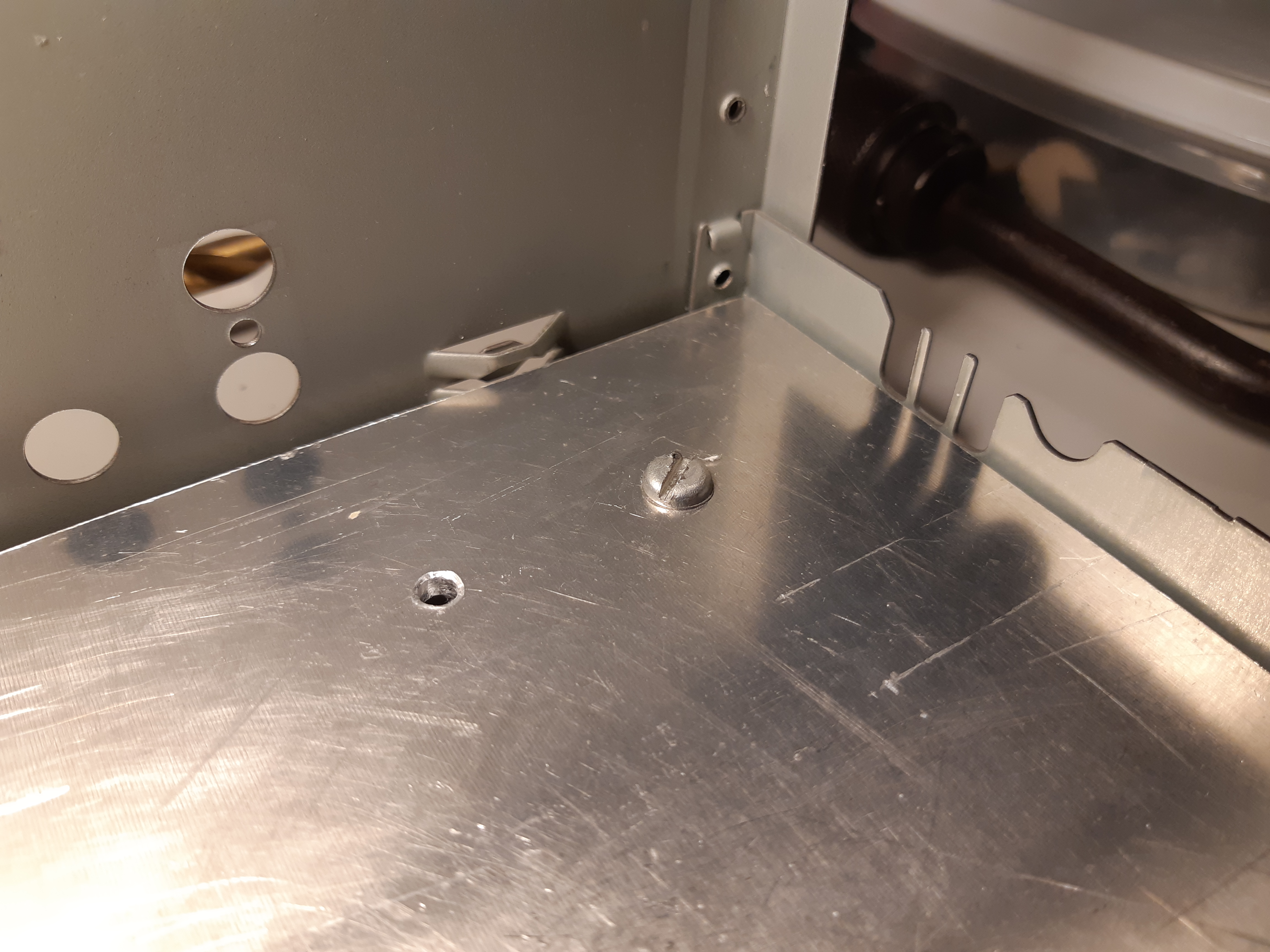
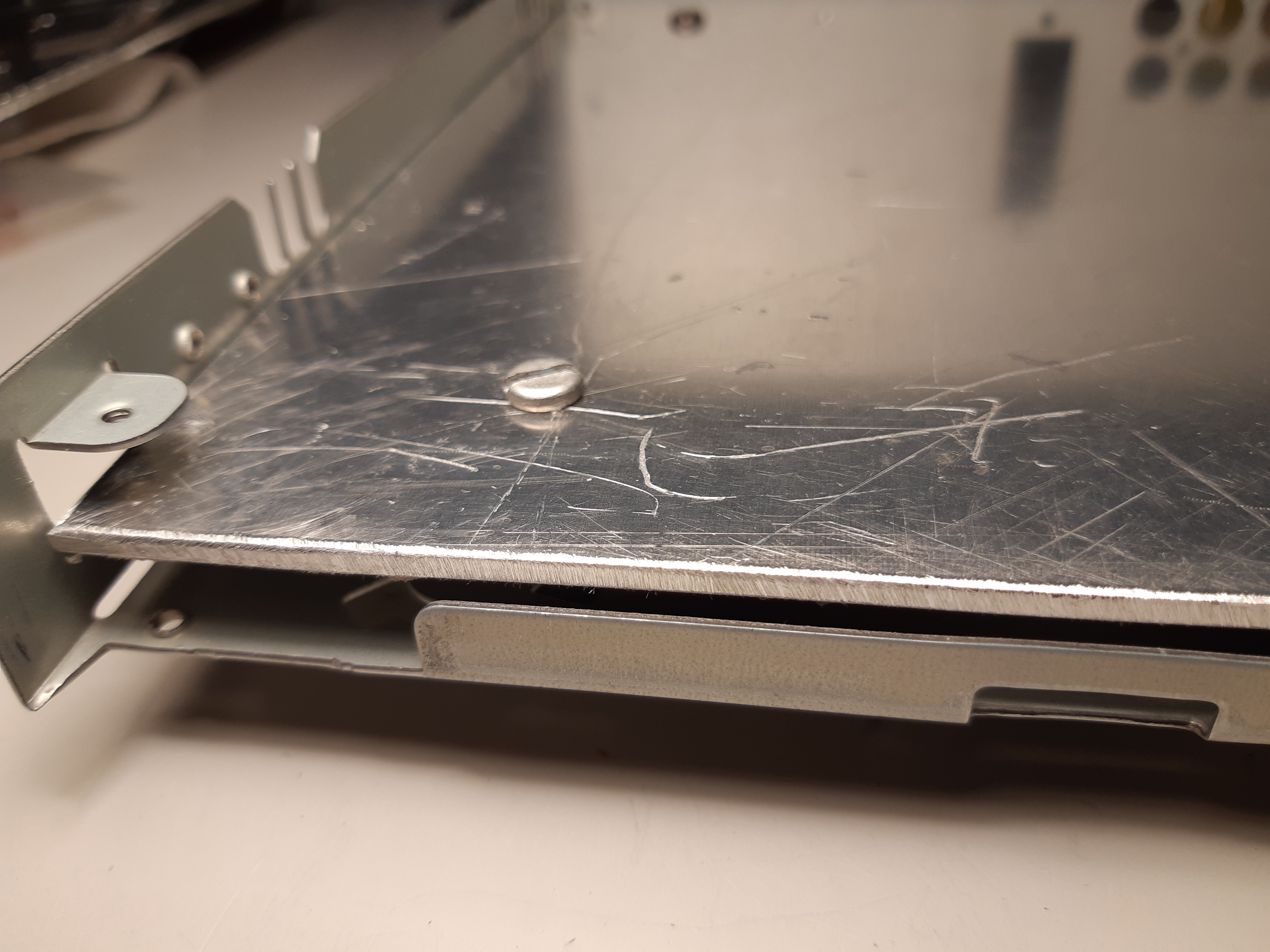
From the bottom, holes for the feet were drilled or re-drilled (front holes were new as the feet got in the way of the panel frame as previously described) right through the blank piece so that the holes align perfectly. Standoffs raising the inside bottom plate and securing it in place will share the same holes as the feet (the upper plate is screw to one end of the standoffs while the bottom cover and rubber feet were screwed to the other end) (figures 52 to 58). After all the hole were drilled, the front panel was reattached using the temporary brackets (fig. 59) and bottom plate was screwed-in.
It was now time to secure the front subpanel permanently. With the temporary brackets holding the front in place, the piece was carefully centered (figures 60 and 61). Pieces of angle bracket, cut from the same stock used to make the heat sink/transistor mount for the power supply, were placed behind the front subpanel so that one side is against the back of the front piece while the one rest on the floor of the chassis, and were held in place temporarily with two-part epoxy glue (figures 61 to 64). When the glue had dried, holes were drilled through the brackets and subpanel or chassis together, and screws were used to secure them (figures 65 and 66). Temporary brackets were no longer needed and were removed.
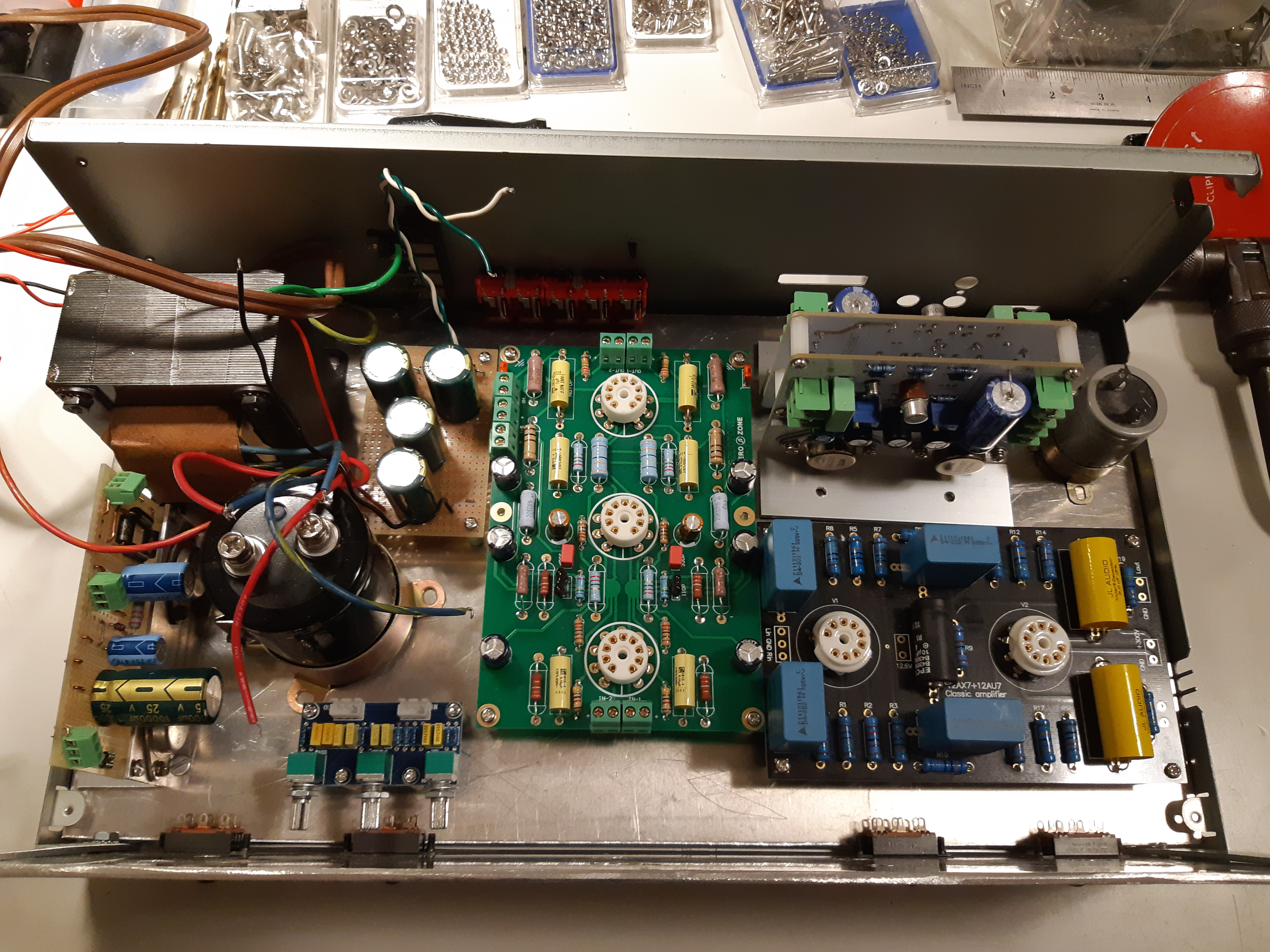
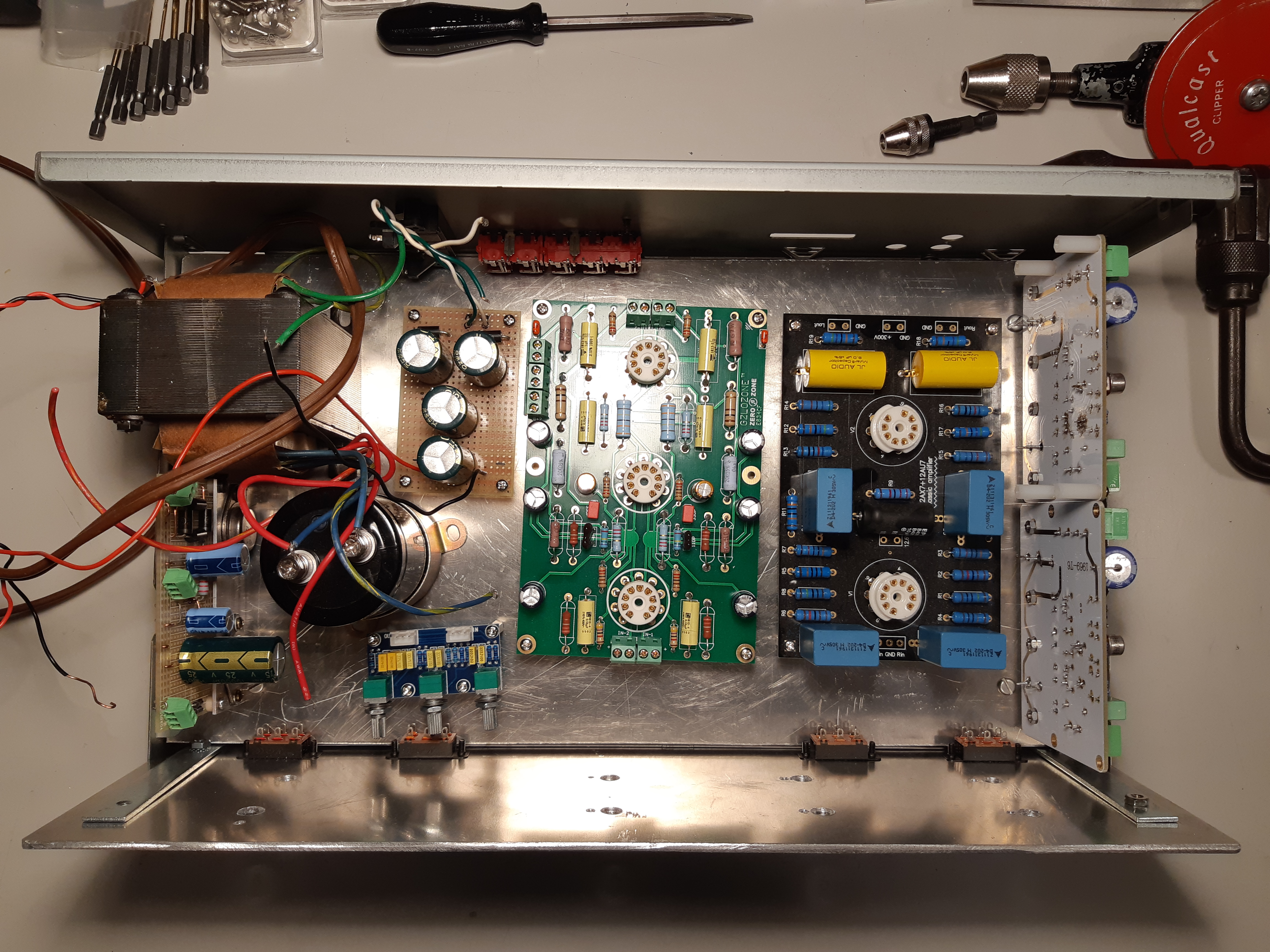
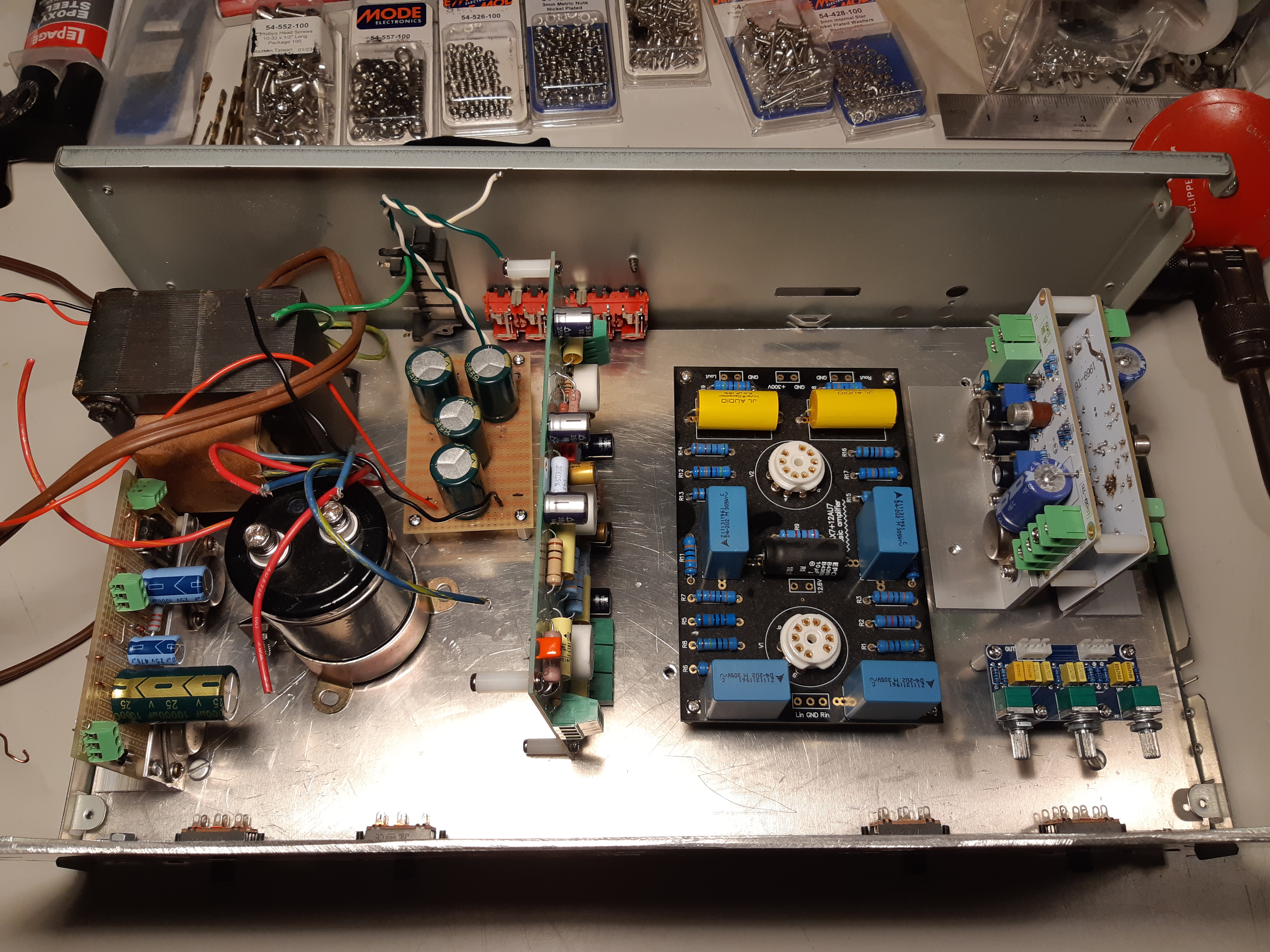
Planning the Layout
The chassis was now ready for component installation. The first step was to plan the layout. This may sound like a simple step but space was limited, height was limited once the top cover is on, and on top of that, components can not be placed in a way so the everything is cramped as some modules can get very hot. Plastic standoffs were added to some of the module boards (fig. 67), then I experimented with various placement configurations, taking a photo of each before rearranging. Nothing was actually hooked up or screwed in place a this time.
In the figures below are just a few of the many test arrangements. I like the third arrangement best (fig. 70) but the top of the board would be too close to the ceiling of the cover and vertical supports would be needed or the board could break while trying to plug-in or replace the tubes.
The Back Panel
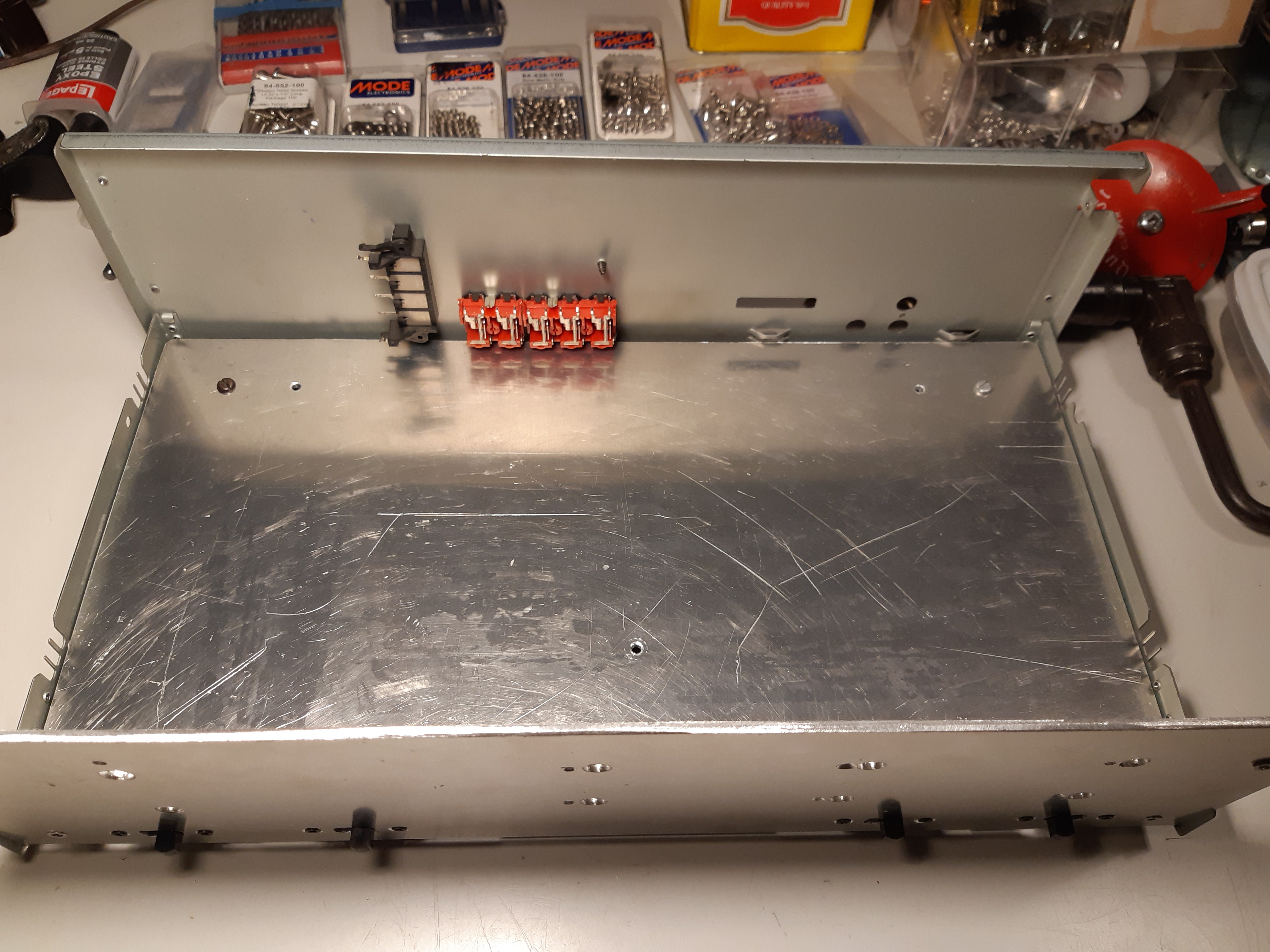
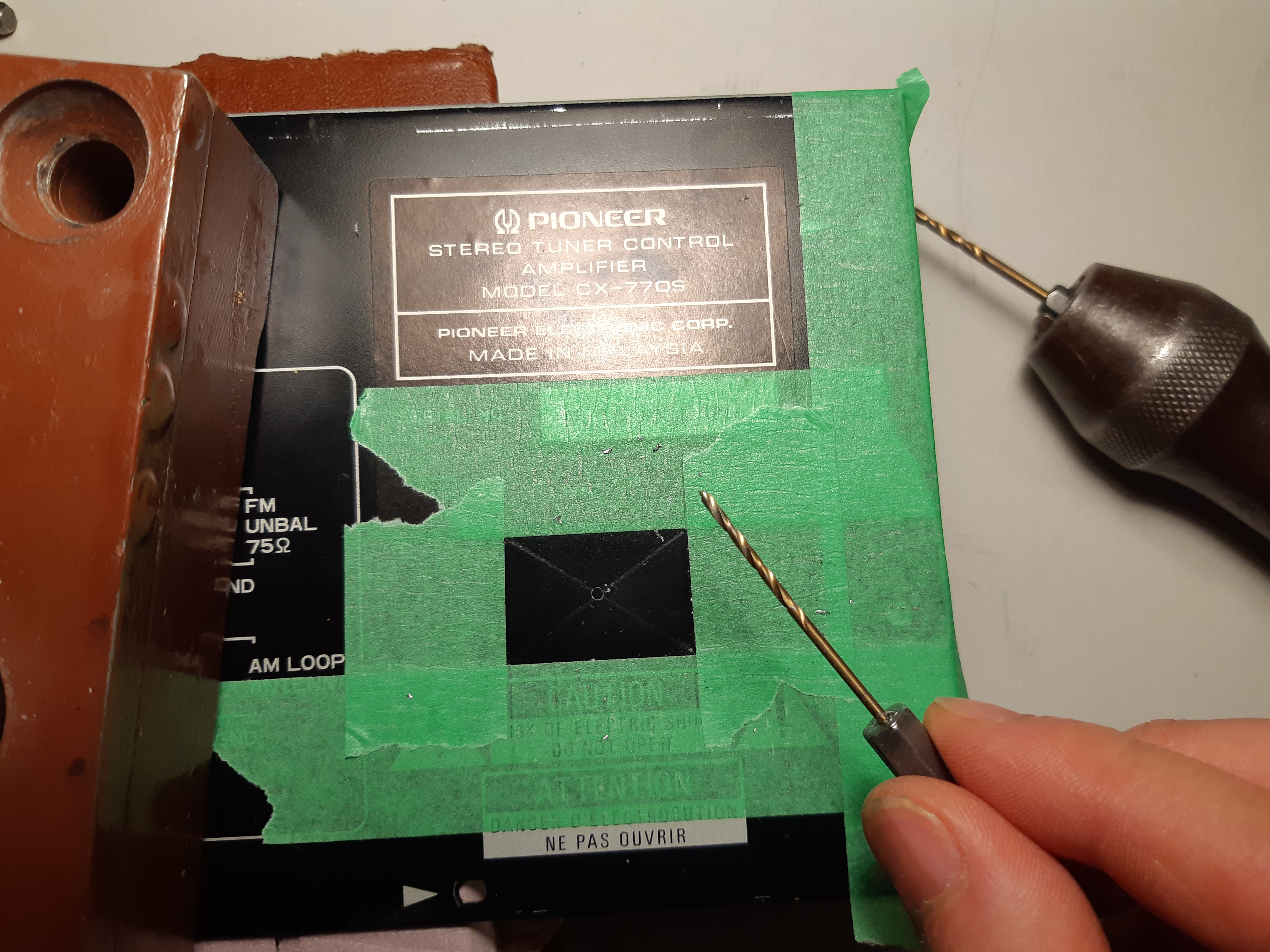
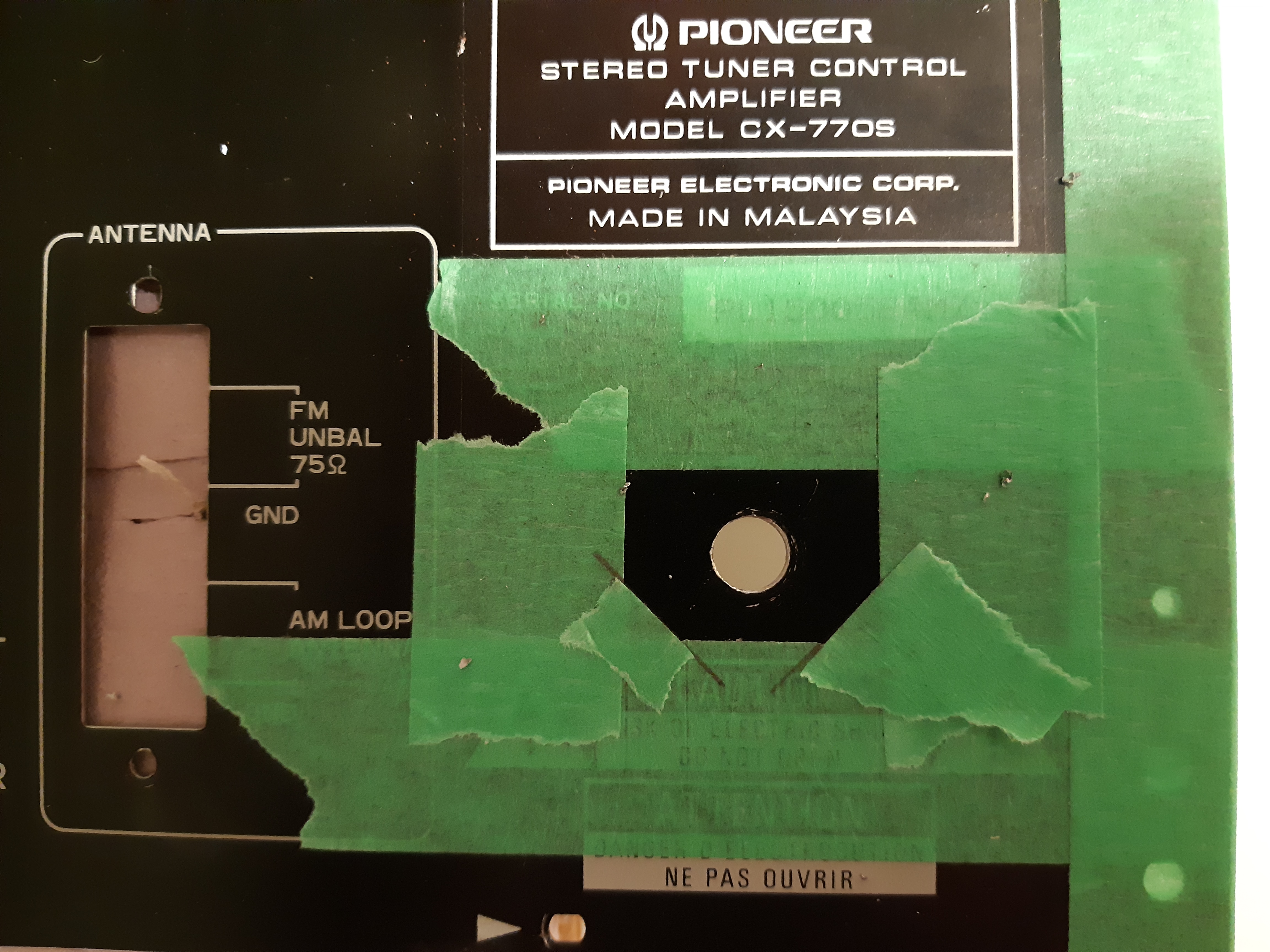
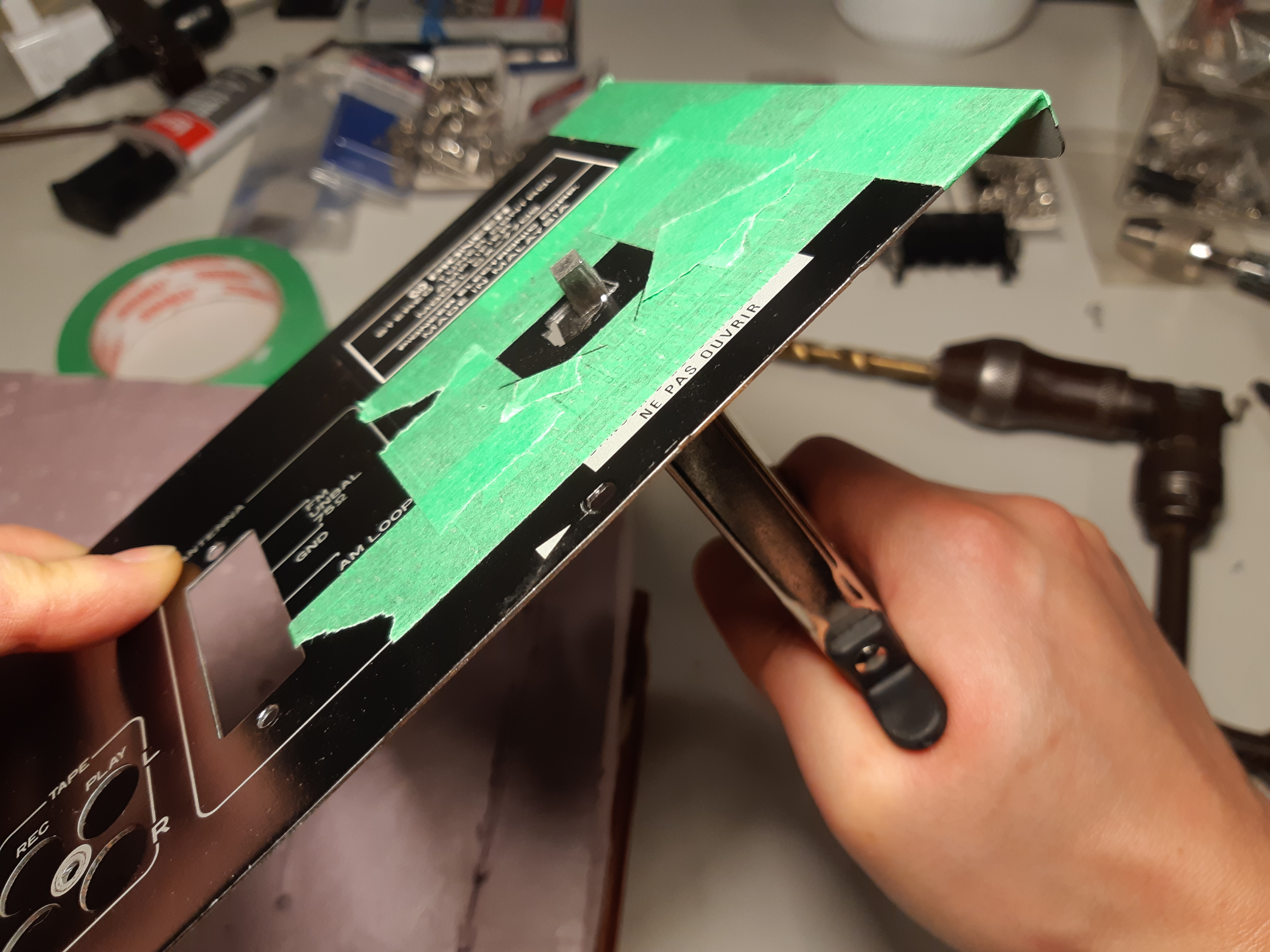
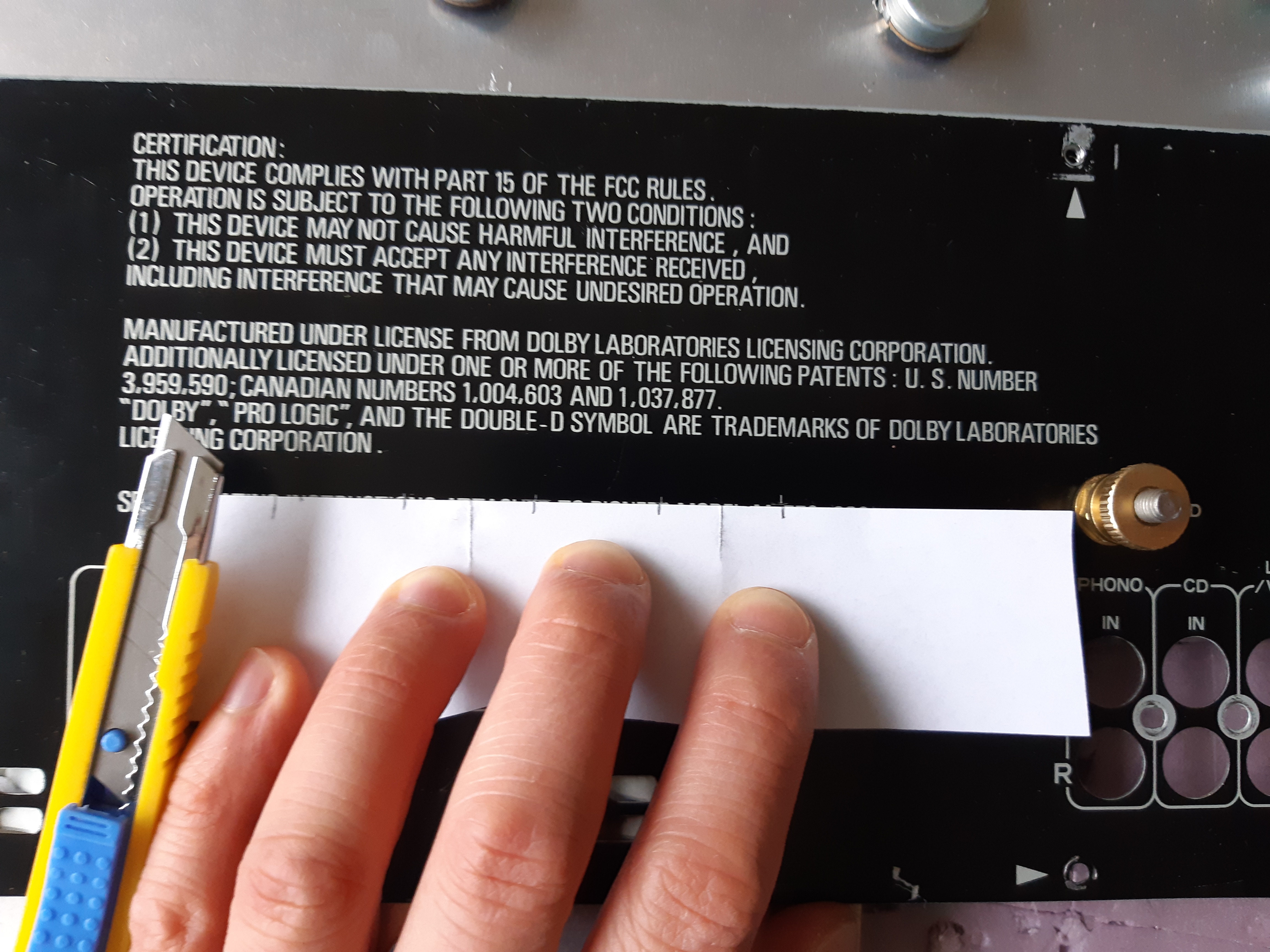
Because the Pioneer CX-770s was a stereo system control box rather than a stereo component itself, there were neither fuses nor power cords, so I would have to add those myself. Returning to my spare parts box, I found a few salvaged IEC 320 C13/C14 power connectors and several matching cords (all of which I was actually about to throw out); I will install one of the connectors at the back. A spot for was chosen on the back panel just behind where the power supply will be located. Measurements of the connector were taken and the selected location was marked on the back of the rear panel with masking tape. The center of the spot was located by drawing an ‘X’ from corner to corner, which was then drilled (beginning with a dent) repeatedly with a brace drill, incrementally increasing the size of the bits until the hole was large enough to insert the head of the nibbler, which was then used to “nibble” away at the hole, forming a rectangular opening for the IEC 320 C13/14 connector. Note: Finding the center was not necessary as this was done out of habit.
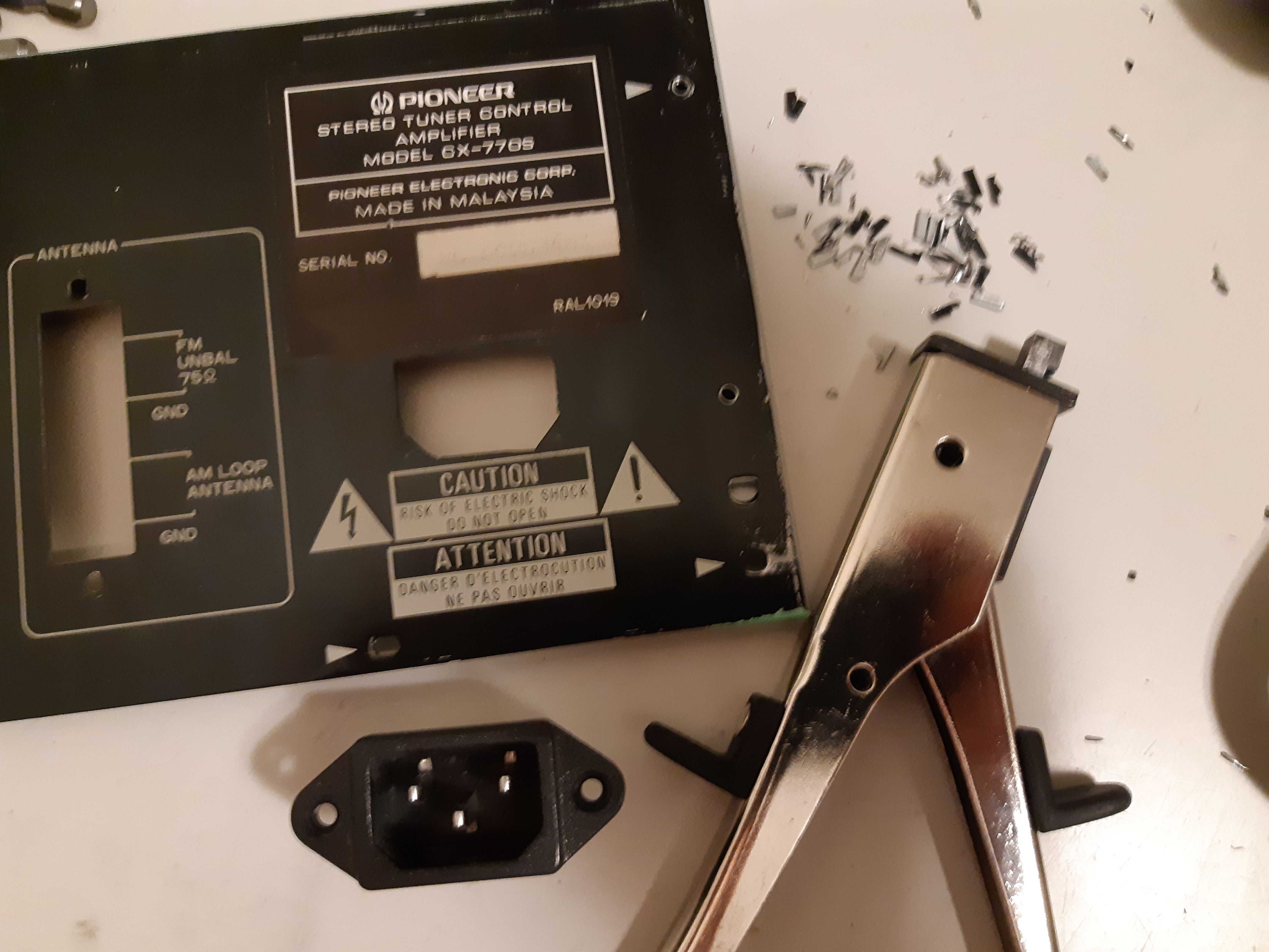
Next, a fuse and accessory power outlet were added. The hole for the outlet was cut in a similar manner. Note: Instead of supplying mains power to the accessory outlet, it will be connected to the second 117 volt winding on the main power transformer supplying an isolated power source at 117 volts (fig. 76).
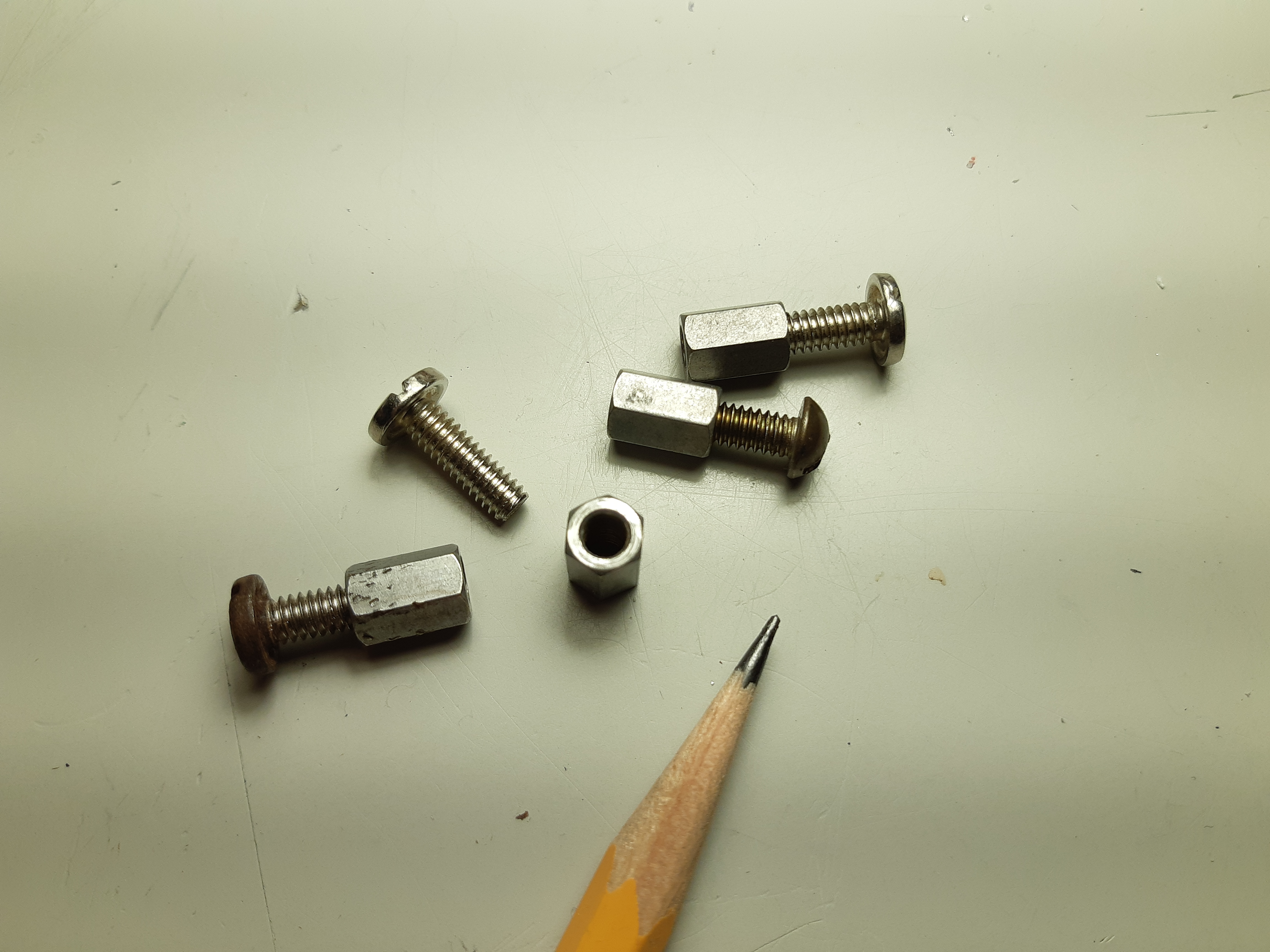
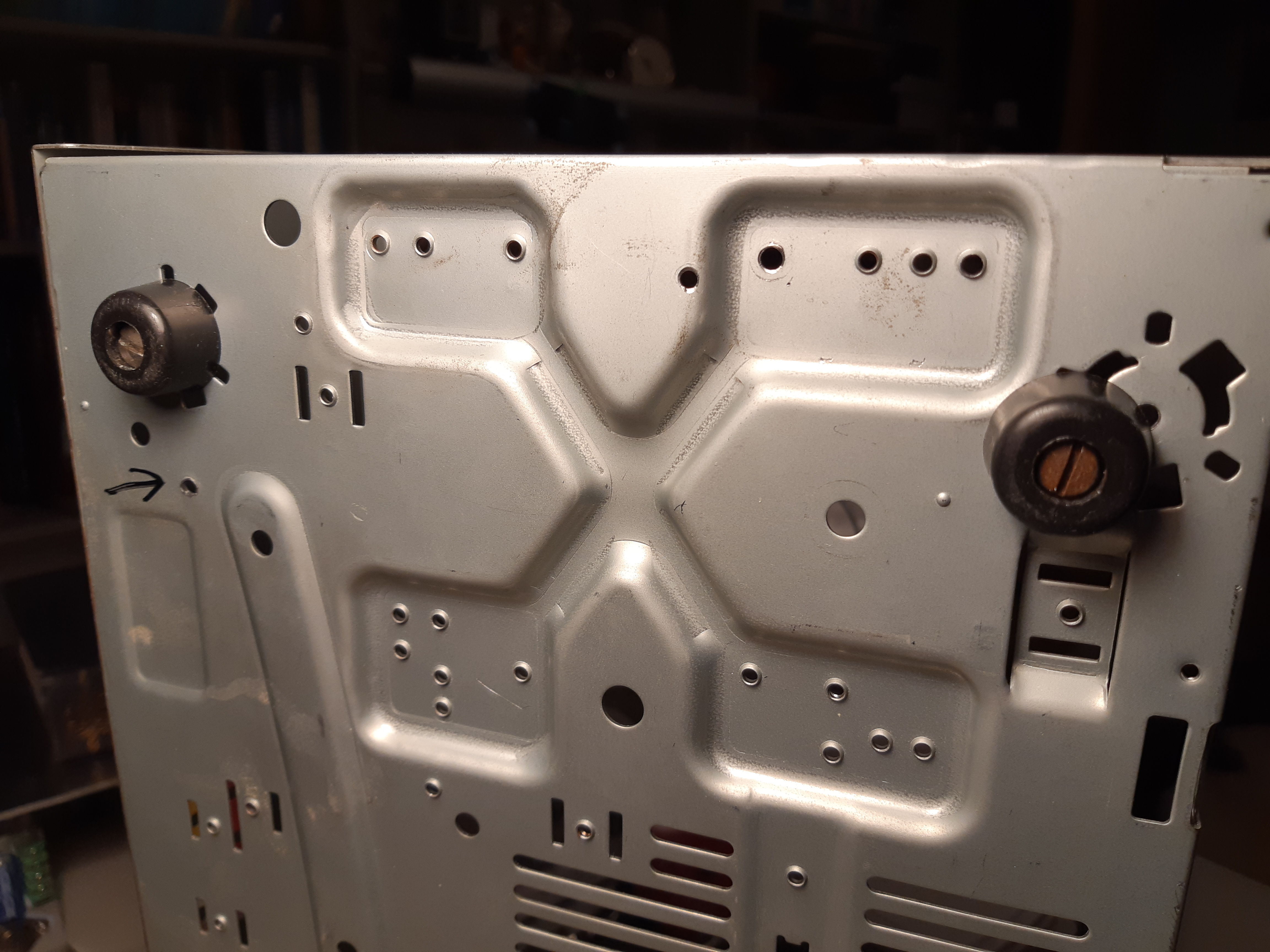
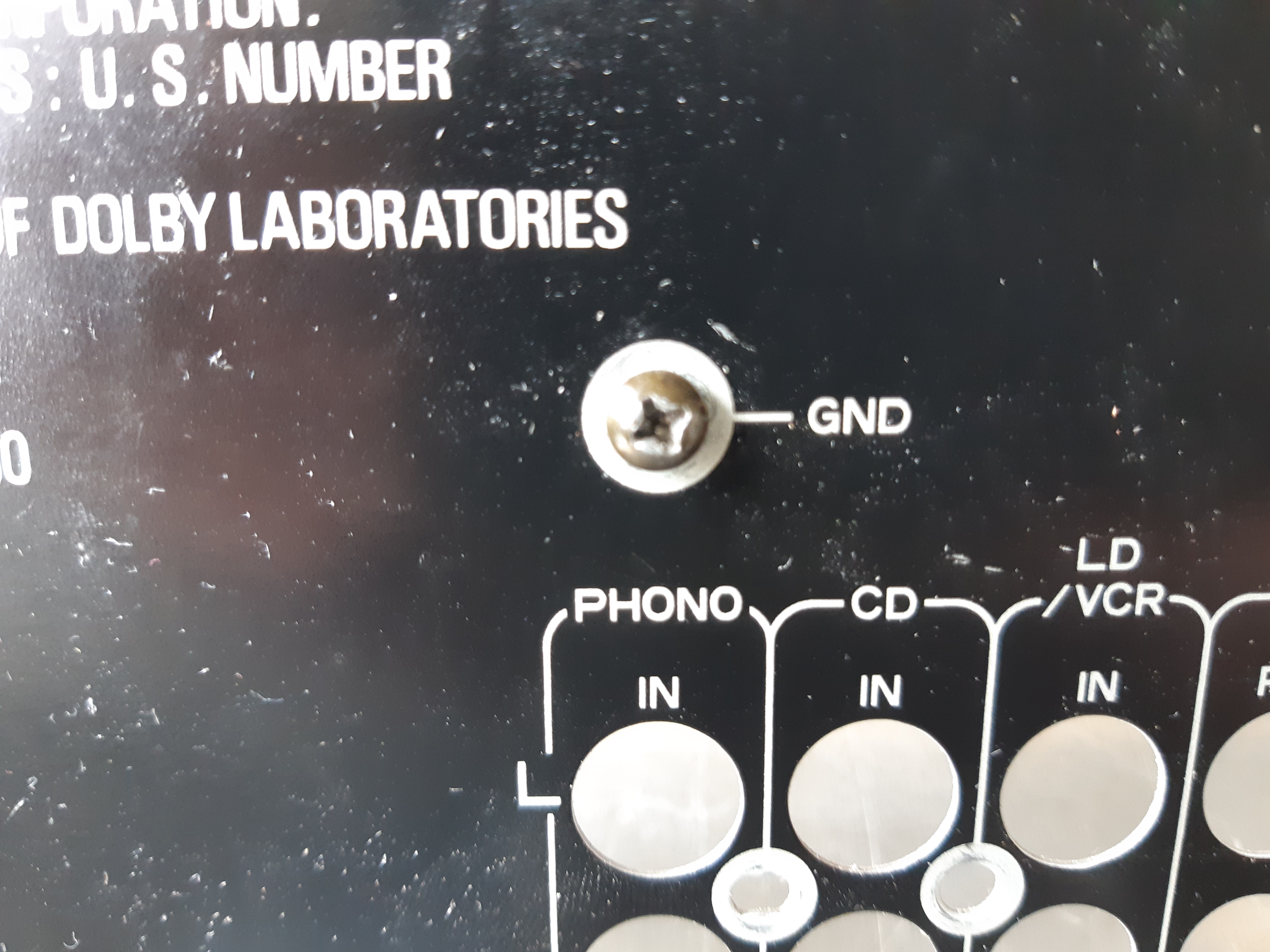
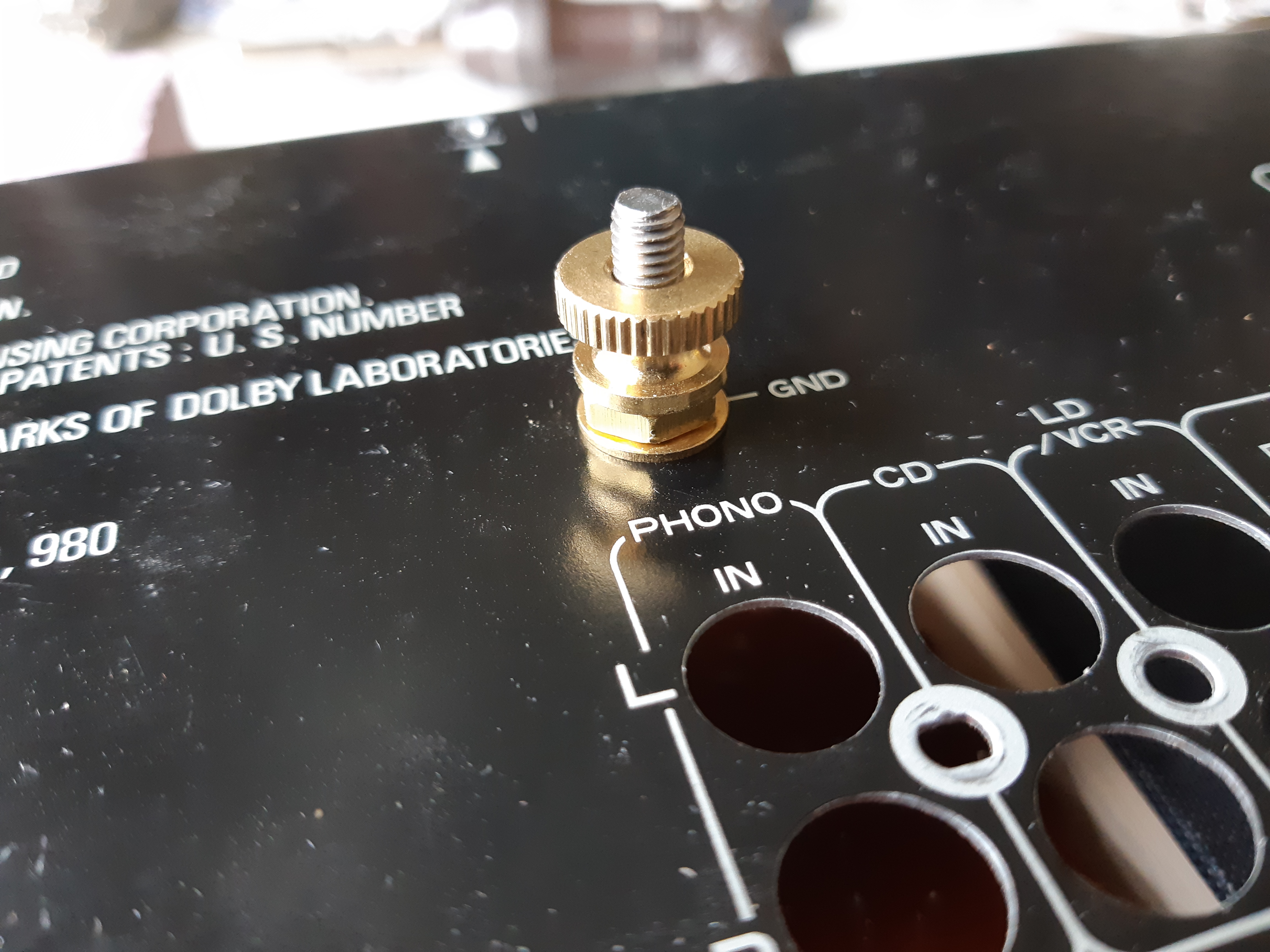
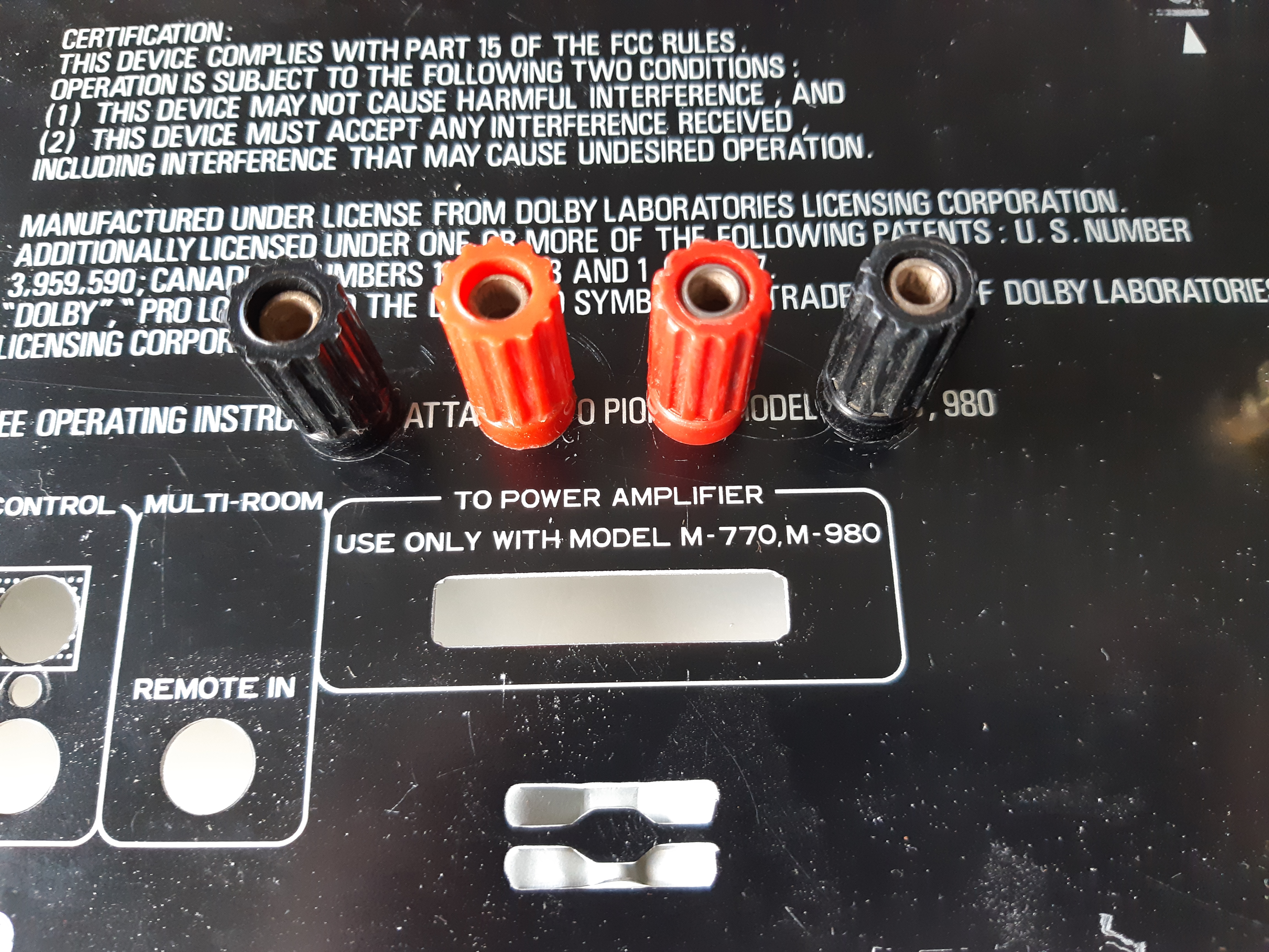
Before moving on to the final assembly stages, the crude looking grounding screw at the back (fig. 77) was swapped out for a nicer looking brass thumb nut binding post.
Speaker terminal were also added to the back. Although this step was actually done much later (after permanent installation of the modules) as I had forgotten about it, I will mention it in this section. In figure 79, holes centers were marked for drilling at a distance of 0.75″ (3/4″) apart as that is the standard distance between centers of speaker binding posts. If I were to purchase these connectors new, I would buy gold plated terminals but since I have several of these from surplus supplies, I’d like to make use of what I already have.
Final Assembly and Wiring
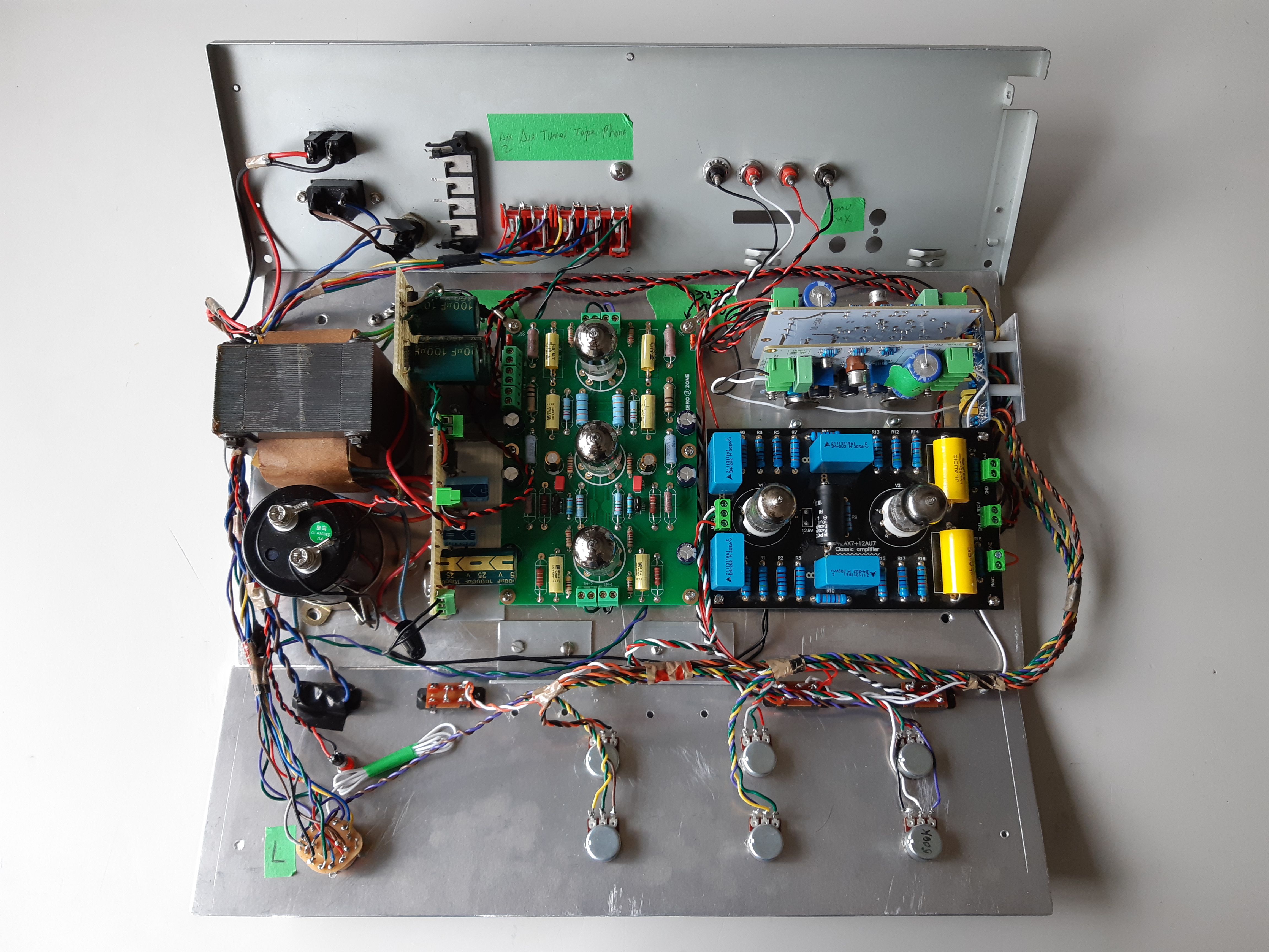
Having selected a layout configuration for the modules and other internal components, it was now time to set them permanently in place. Measurements were made of the components (i.e. distances between centers of screw holes) and marked on the chassis with a paint pen and holes were drilled (fig. 82). Bottom cover was then removed via the four screws connecting the top plate to the standoffs (added and described earlier) so that some of the components could be screwed in from the bottom side of the chassis plate. Standoffs (for the modules) were added first to the chassis without the boards (fig. 83). The transformer and heatsinks were also screwed from below and bolted on top due to limited space between the chassis plate and bottom cover (fig. 84).
Before reattaching the top of the chassis to the bottom piece, a very annoying tab protruding from the bottom cover was removed as it served no purpose other than make it difficult to remove or reattach the chassis plate (figures 85 and 86).
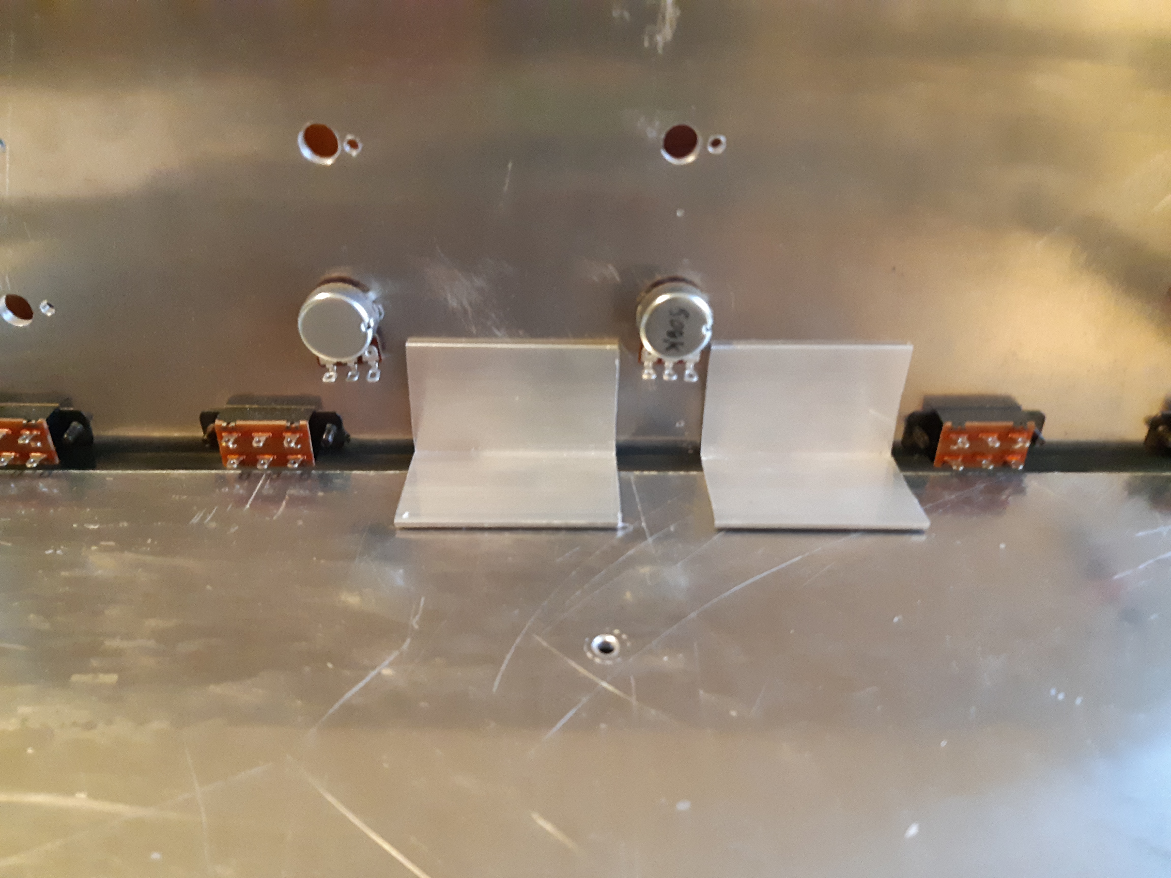
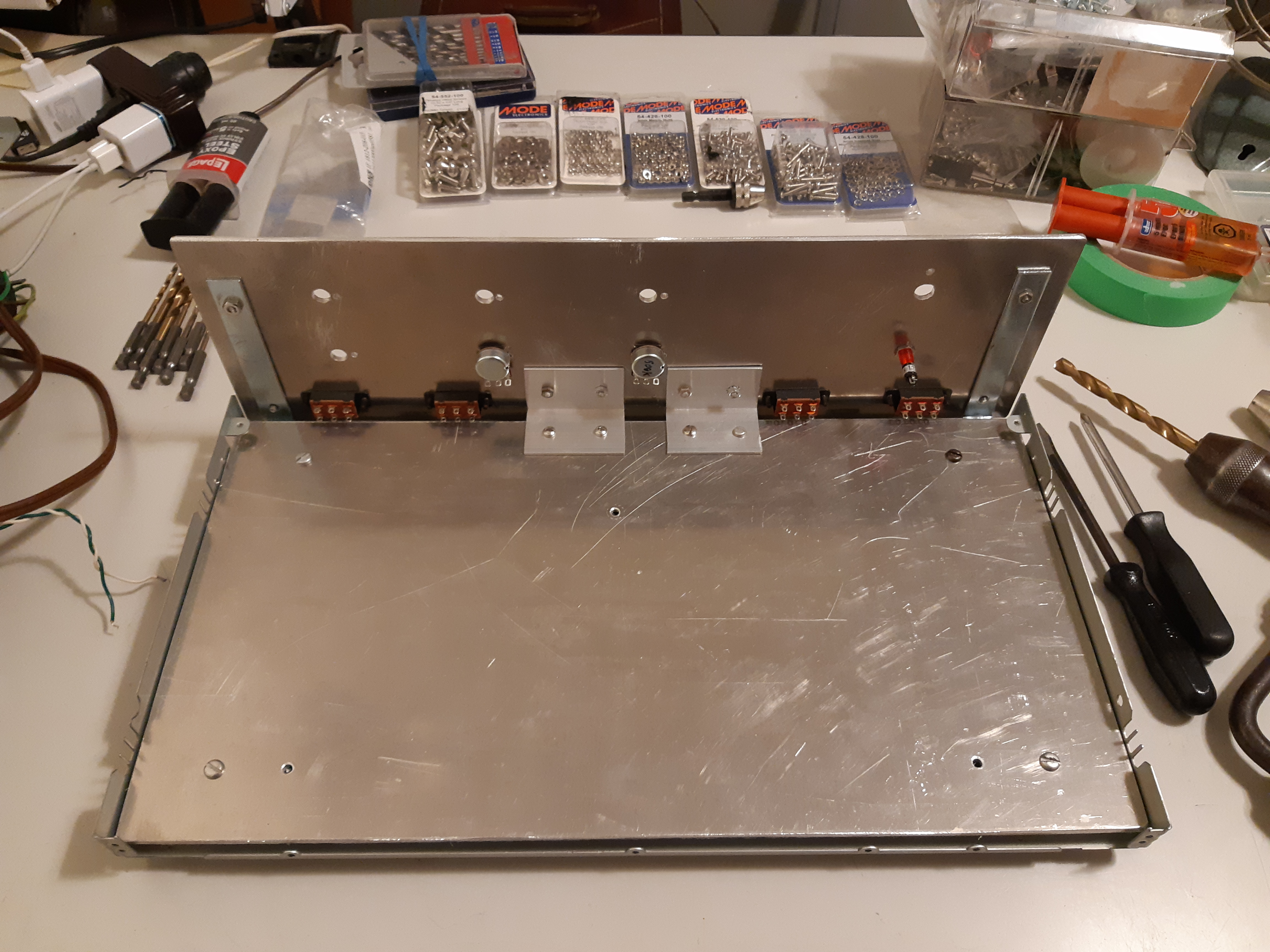
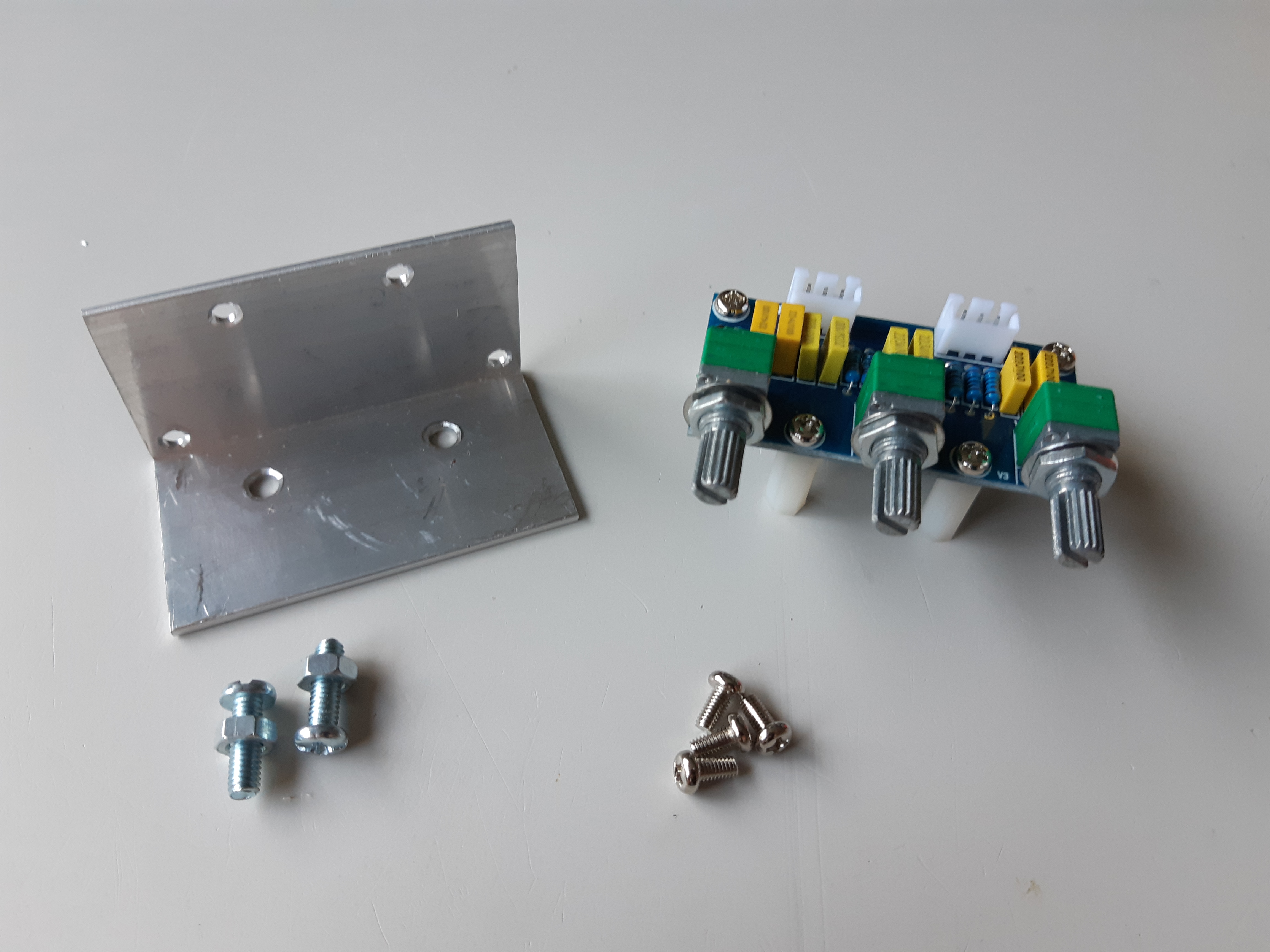
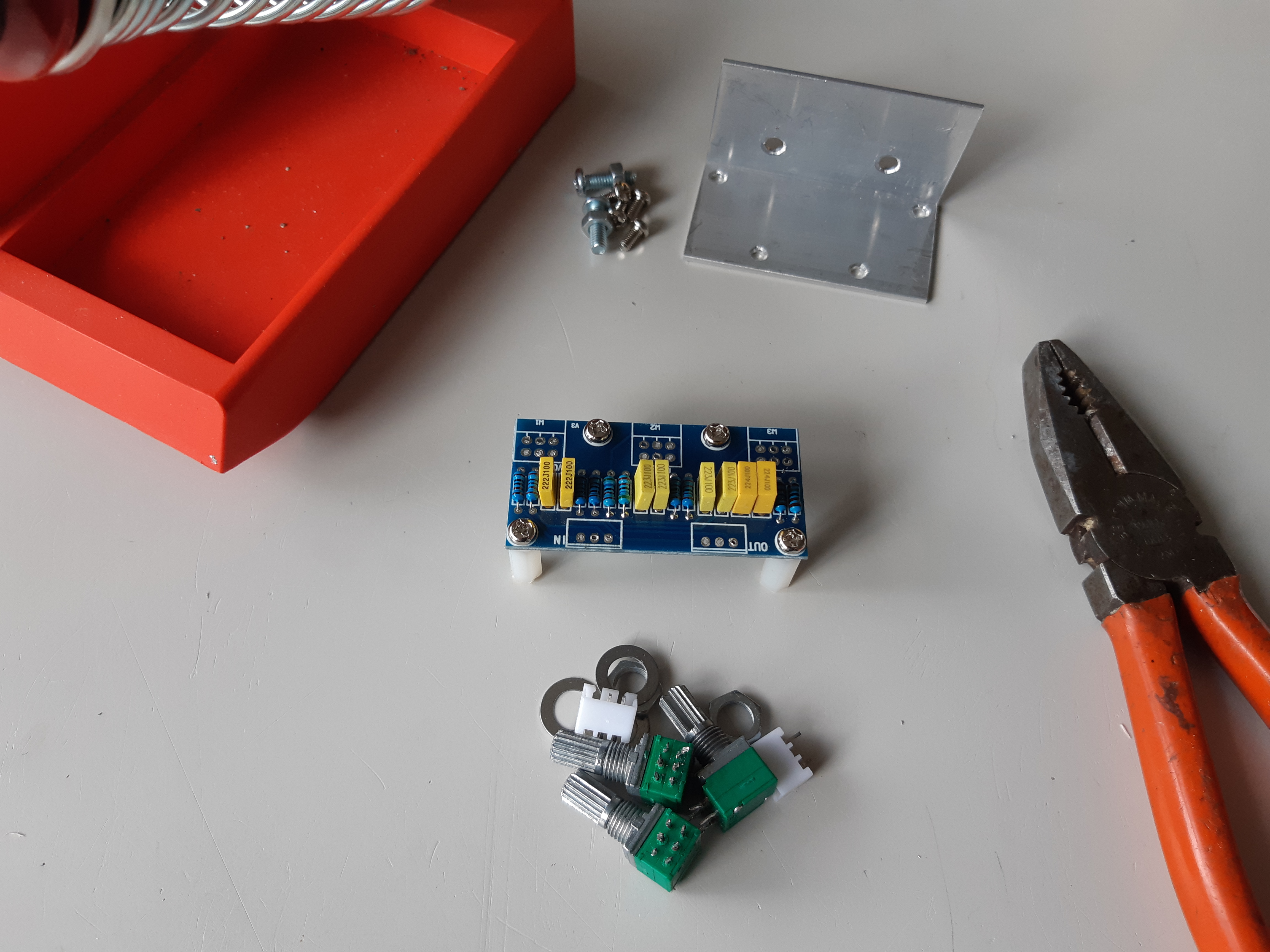
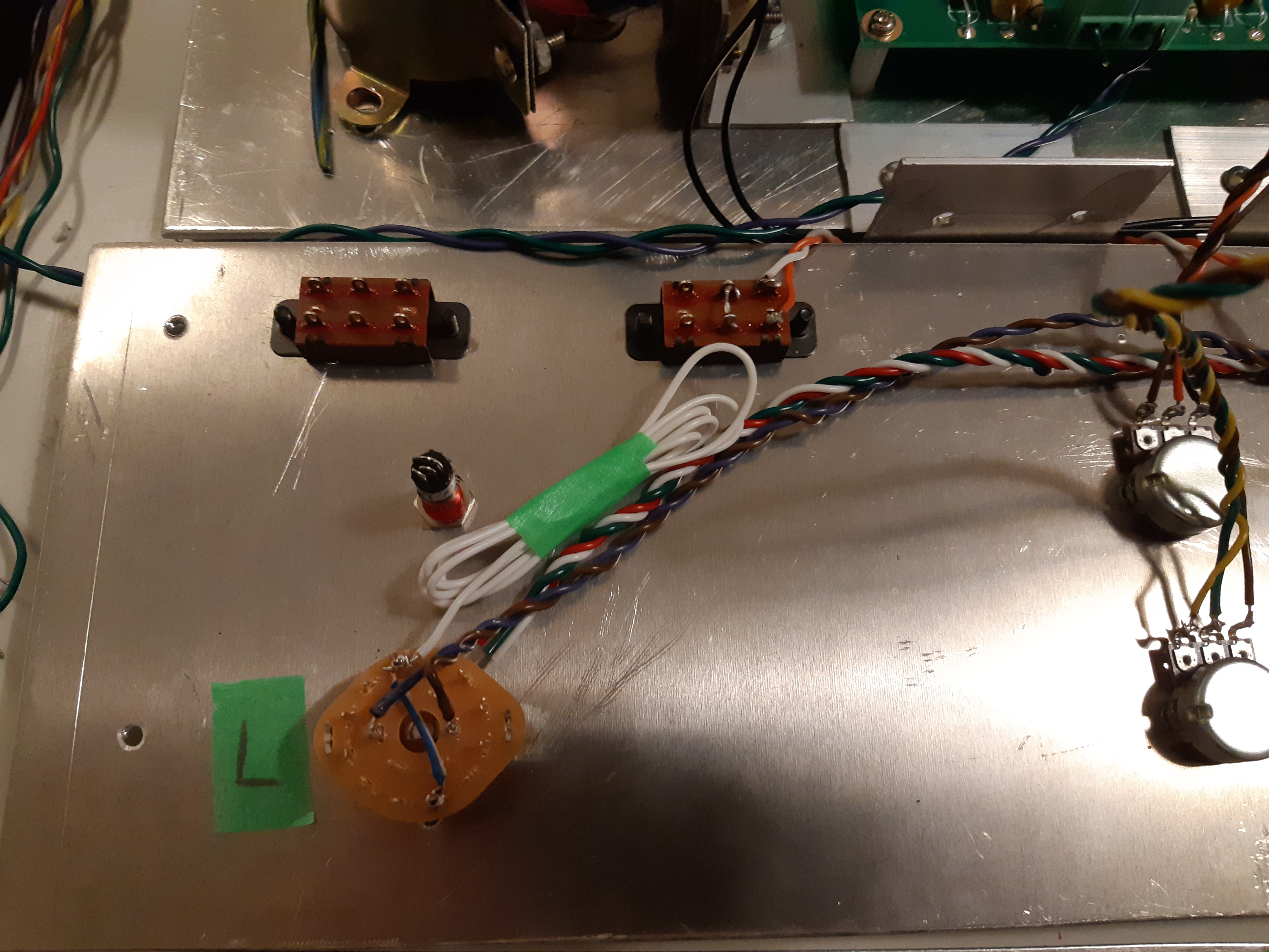
Just before installing the boards, a stand for the tone control board was made from a section of angled bracket. The original pots (variable resistors used controls or potentiometers) were de-soldered from the board and replace with wires that will run to the pot (bass and treble controls) on the front panel (figures 87 and 88).
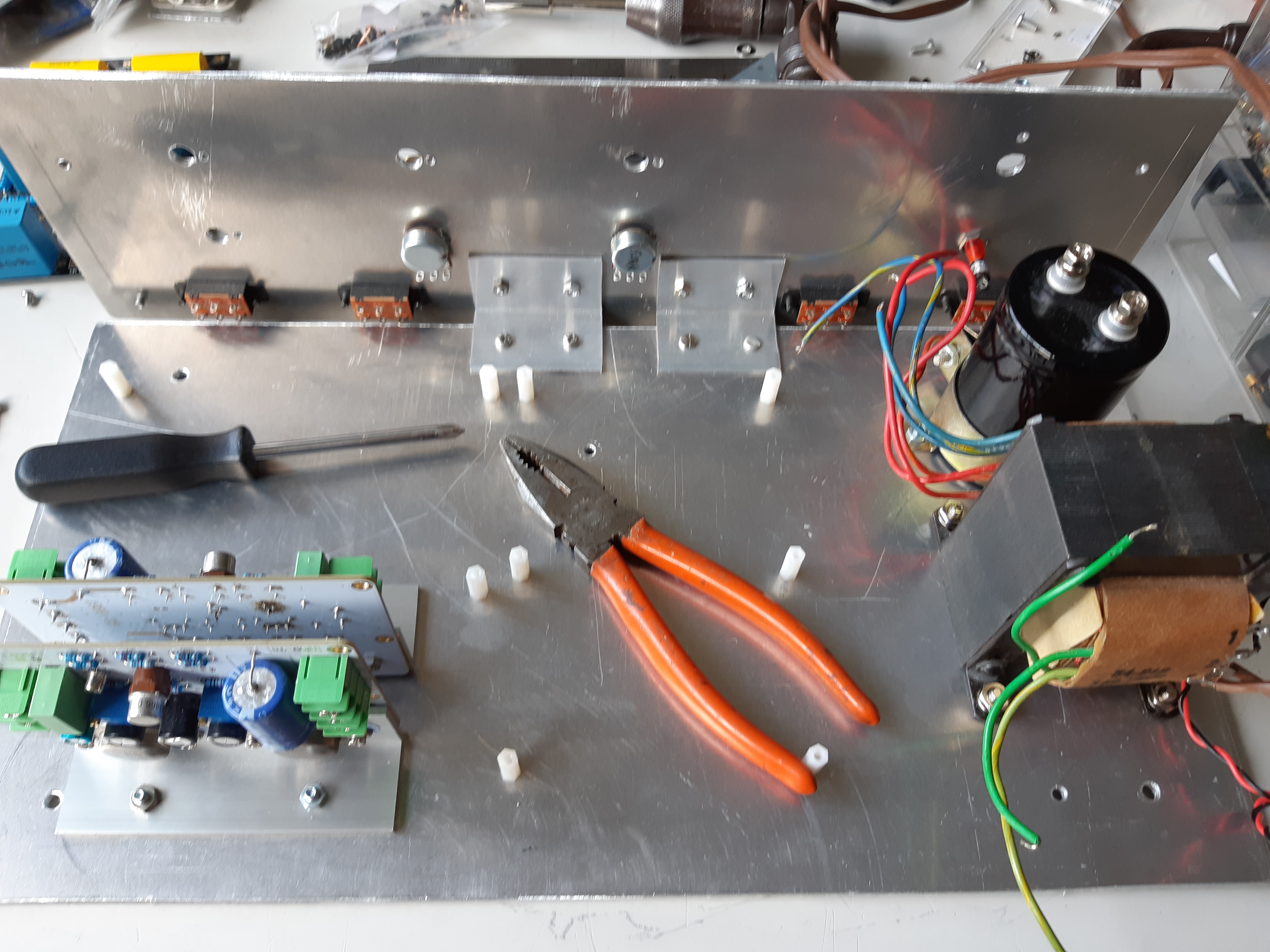
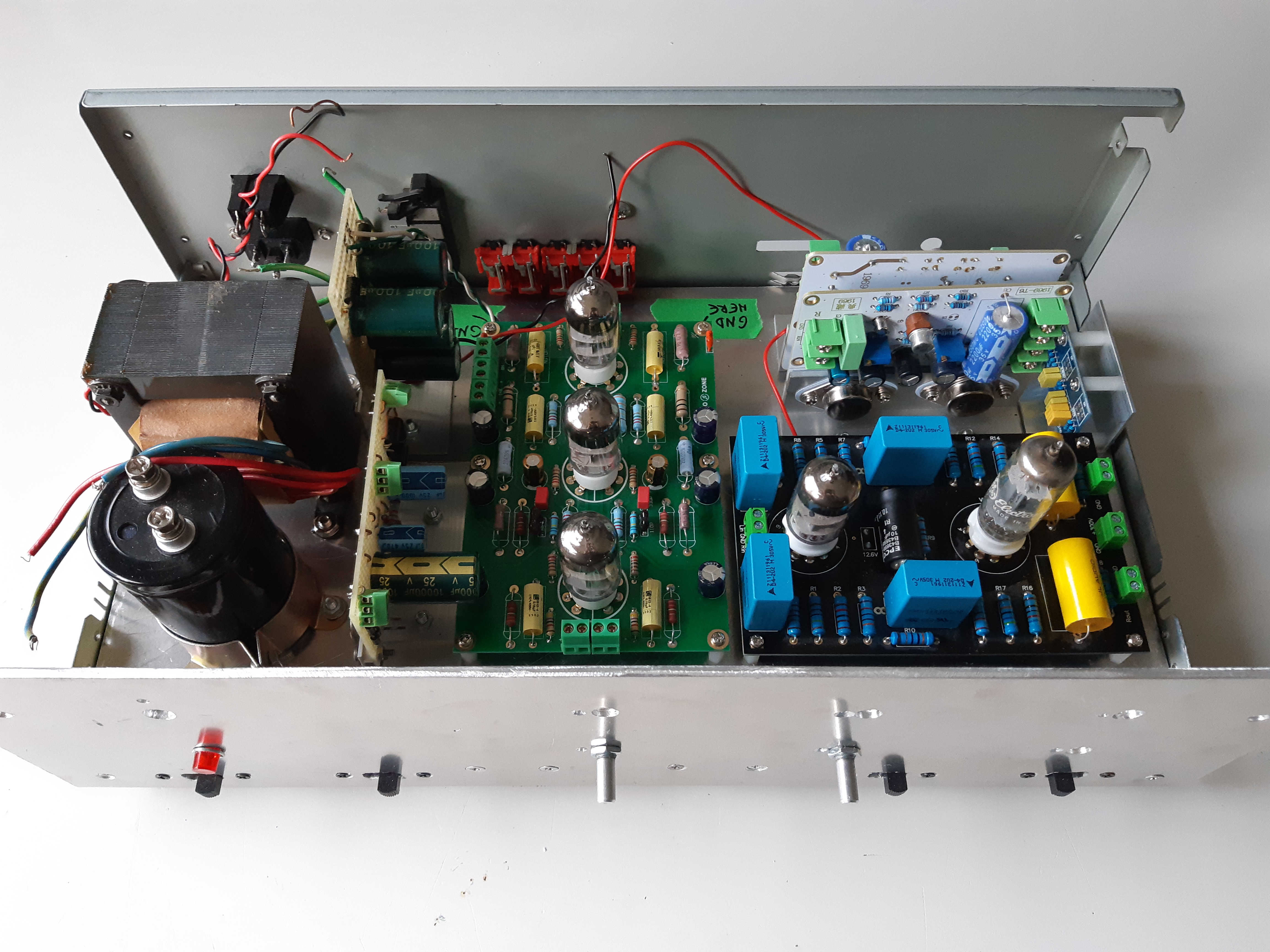
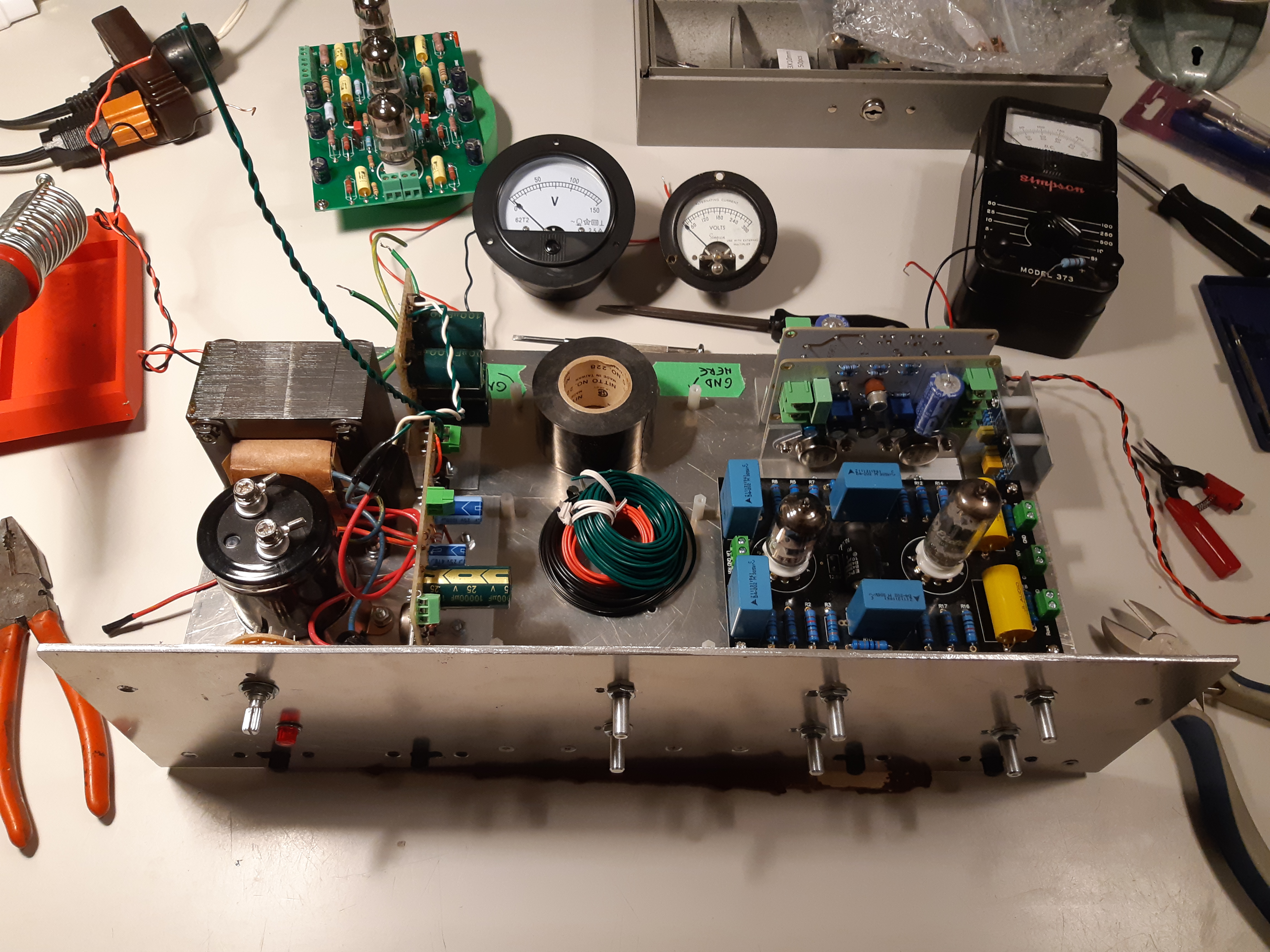
Then rest of the components were then installed in place (figures 89 and 90).
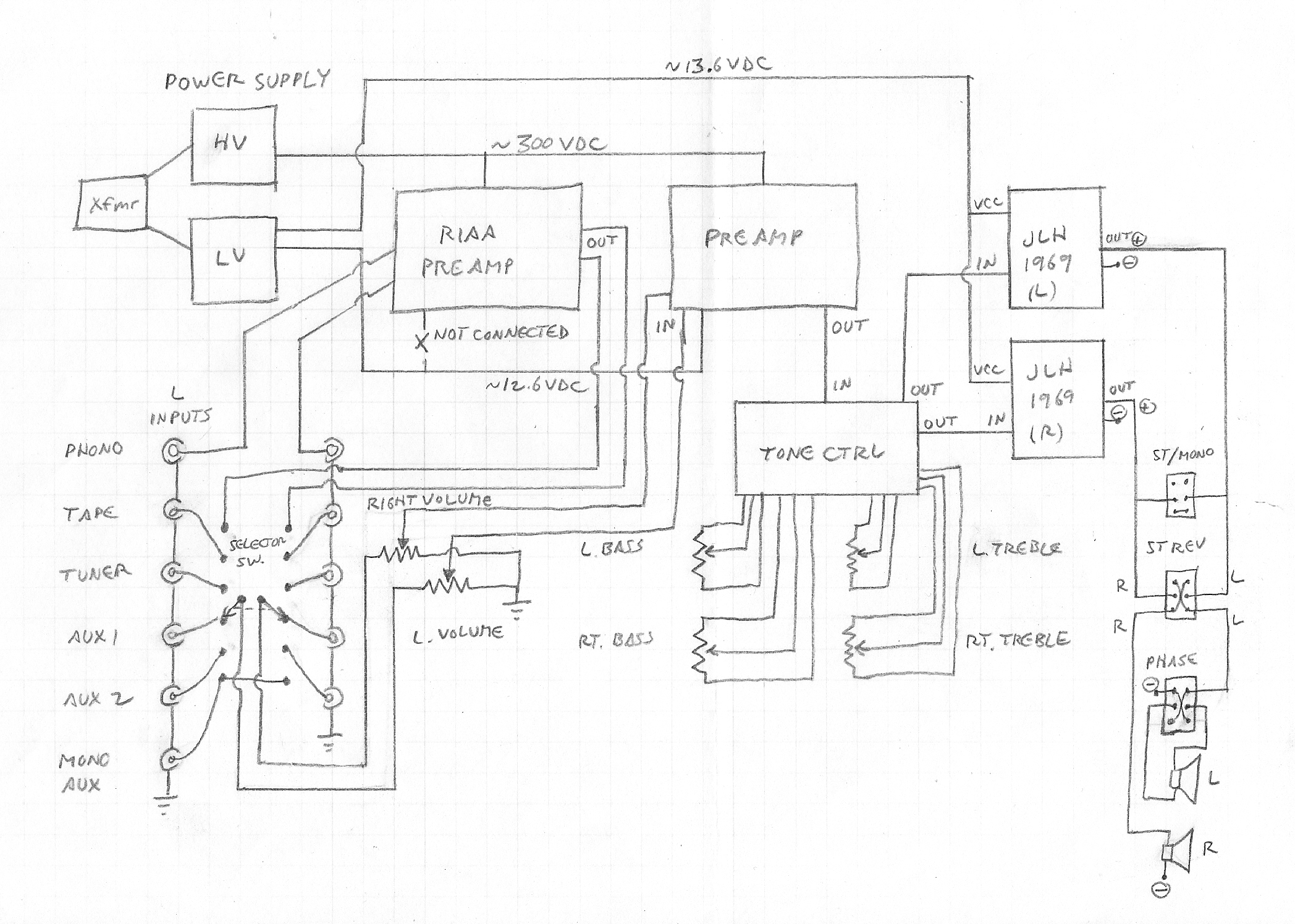
Before wiring everything together, it’s a good idea to map out a wiring plan to reduce the chances of mistakes. Below, is a wiring plan I have drawn for this project (click on image below to enlarge).
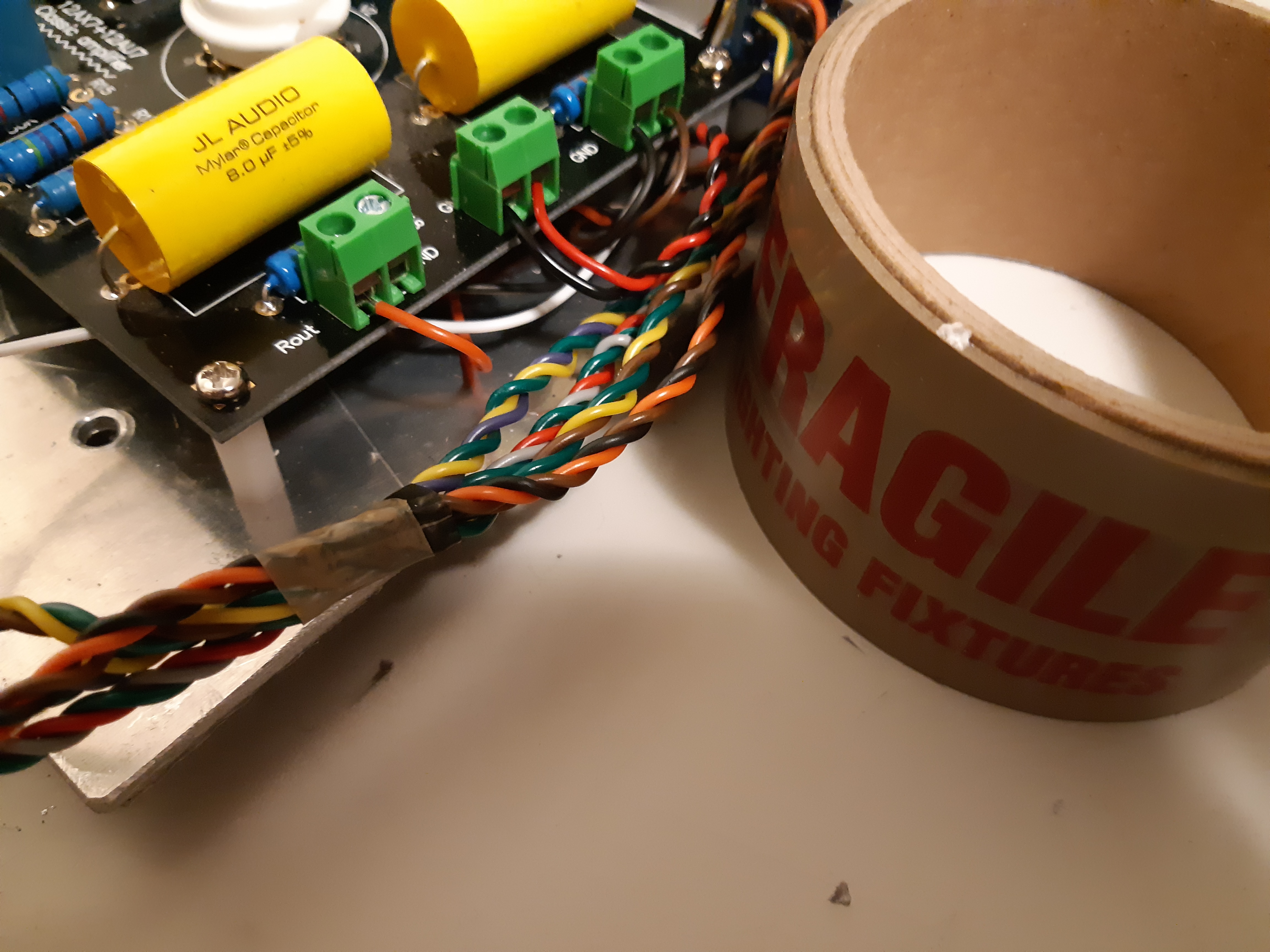
Components were then wired together. For many projects, this can get messy; to keep everything neat and tidy, wires were twisted together in pairs (fig. 92) and bundled together with “fragile” shipping tape (fig. 93). To access connectors, some of the boards had to be removed temporarily (fig. 94).
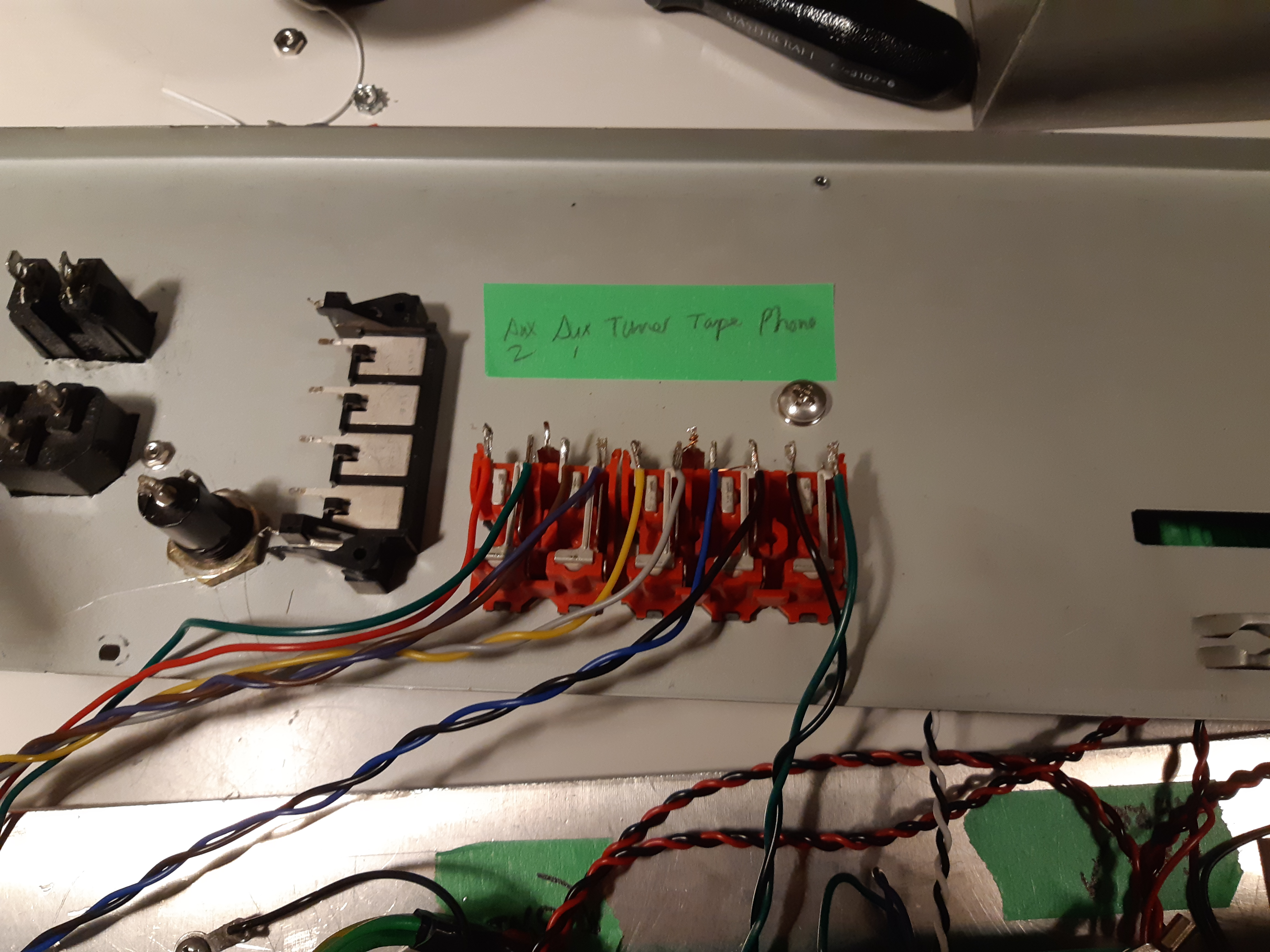
The mono auxiliary input line – intended for my tube-type radio communication receivers (“boatanchor” radios), “police” scanner, and two-way radio base stations – will be connected to an RCA jack on the rear panel later. The “MONO AUX” input could also be used with my crystal set but for now, with one end of the line soldered to the selector switch, I have bundled the “MONO AUX” input line with masking tape and made a note of it (fig. 95).
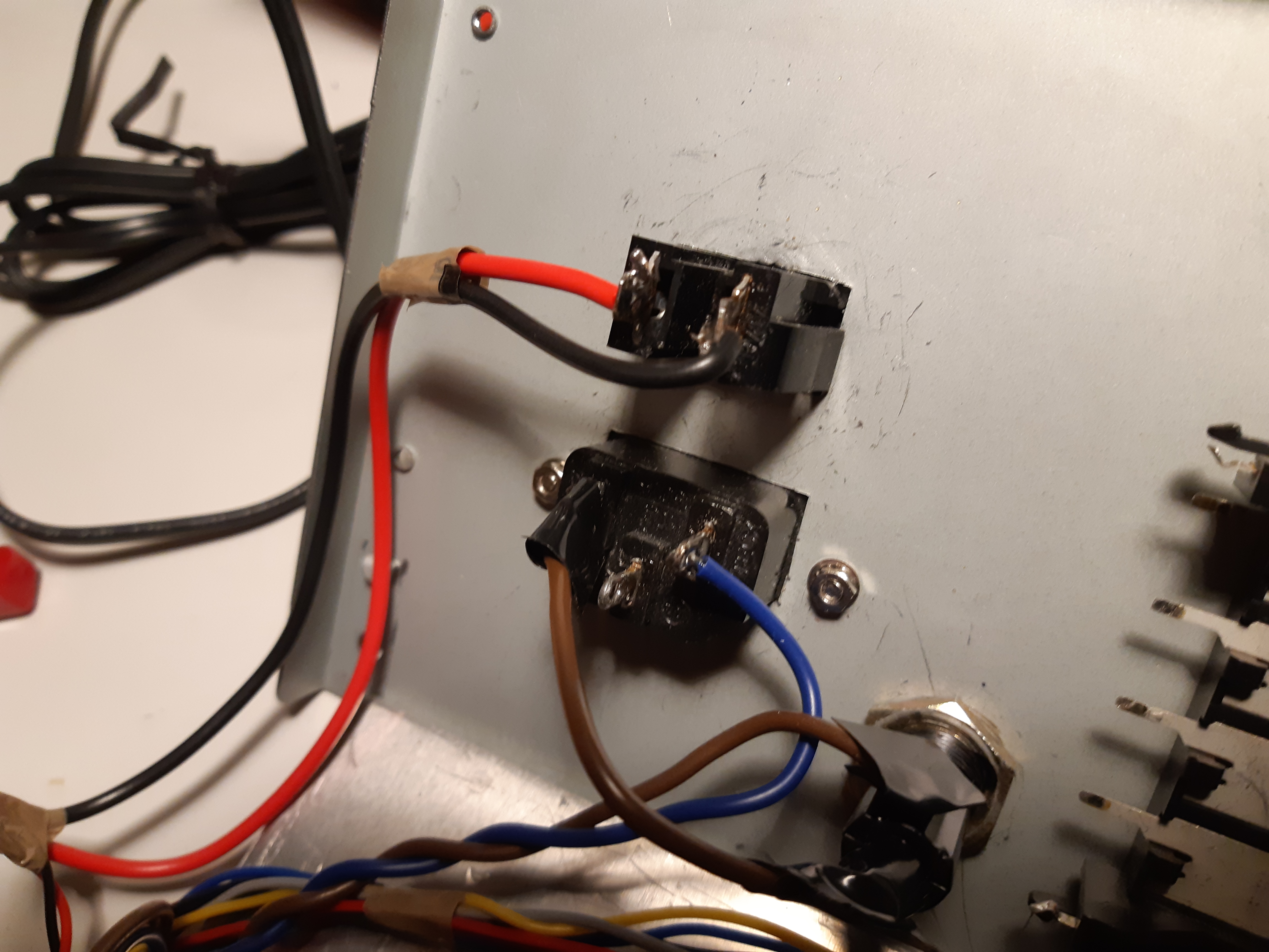
To wire the main AC power line, the incoming “hot” side of the line was wired from the power cord connector to inner tab of the fuse holder, the other tab of the fuse holder was wired to one side of the double pole switch, from the switch to the transformer, from the transformer back to the other side of the switch, and out to the other tab (neutral) of the power cord conductor. If you are using a single pole switch, always switch the “hot” side of the AC power line. The reason for this is to ensure that the rest of the equipment is not connected to the hot side of the AC line when the switch is off (open). Note the electrical tape covering the solder tabs of the AC power switch in figure 96.
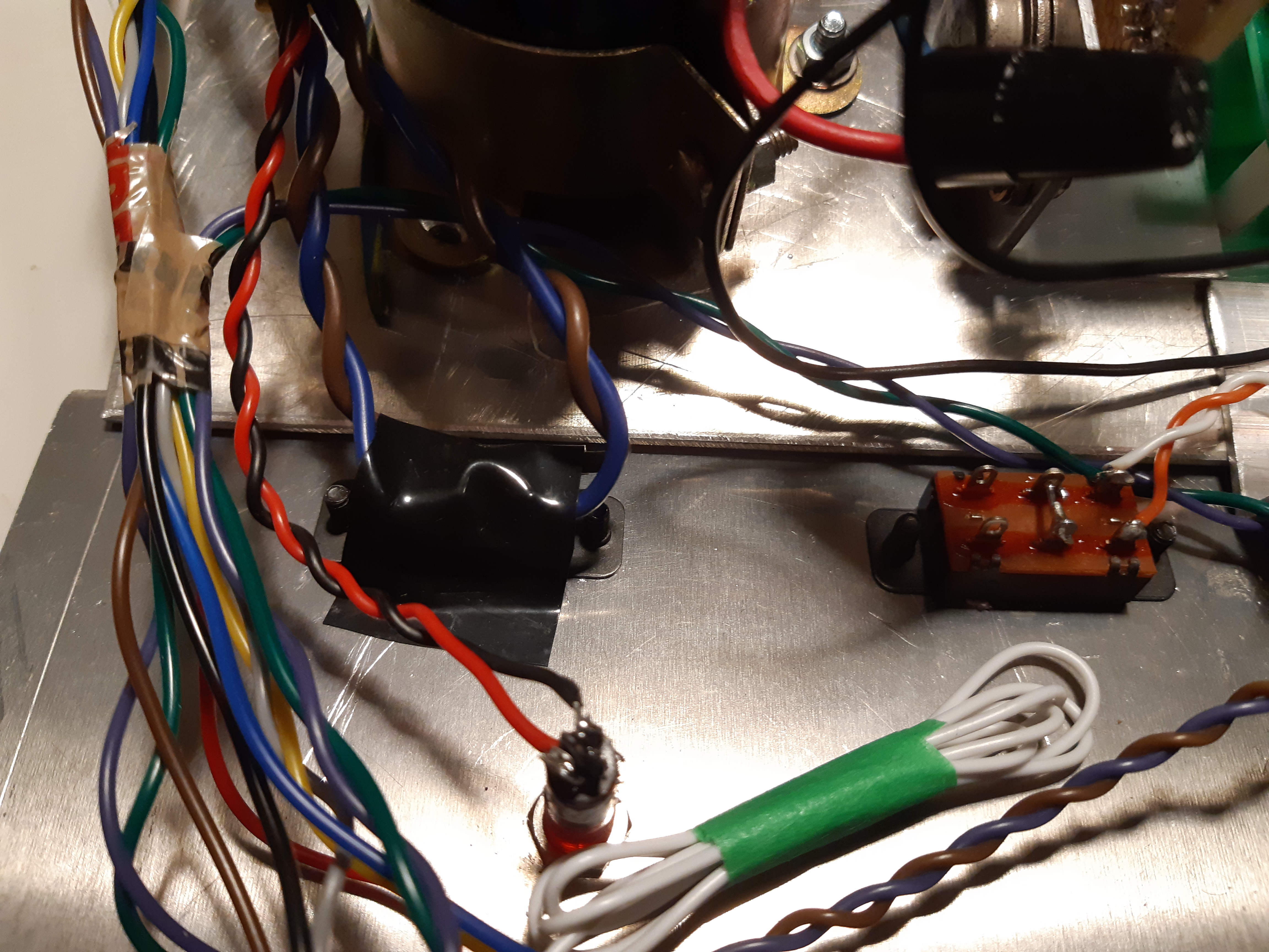
The accessory AC outlet is connected to the other 117 volt winding that is NOT used as the 117 volt primary (fig. 97). This outlet will supply isolated AC at 117 volts.
As previously mentioned, if the center tap of the 12AX7 and 12AU7 tubes are grounded, the filament or heater supply can not be grounded to the same ground if you are using 12.6 volt AC or DC; otherwise, one of the two triodes within the tube will get too much voltage and possibly melt the cathode while the other triode will not work at all. Since I have opted to use DC rather than AC on the filaments (to eliminate annoying filament hum), the problem is that the 12.6 volt supply does indeed have a grounded negative, sharing the same ground with the center tap of the filaments. The problem was easily solved by disconnecting pin 9 (tube pin numbering is always from clockwise bottom view). This was done by de-soldering the tabs on the tube sockets leading to pin 9, pulling them out and bending up and away from the board (or you just cut the tab off but I chose to leave it there) (fig. 98).
This completes the wiring.
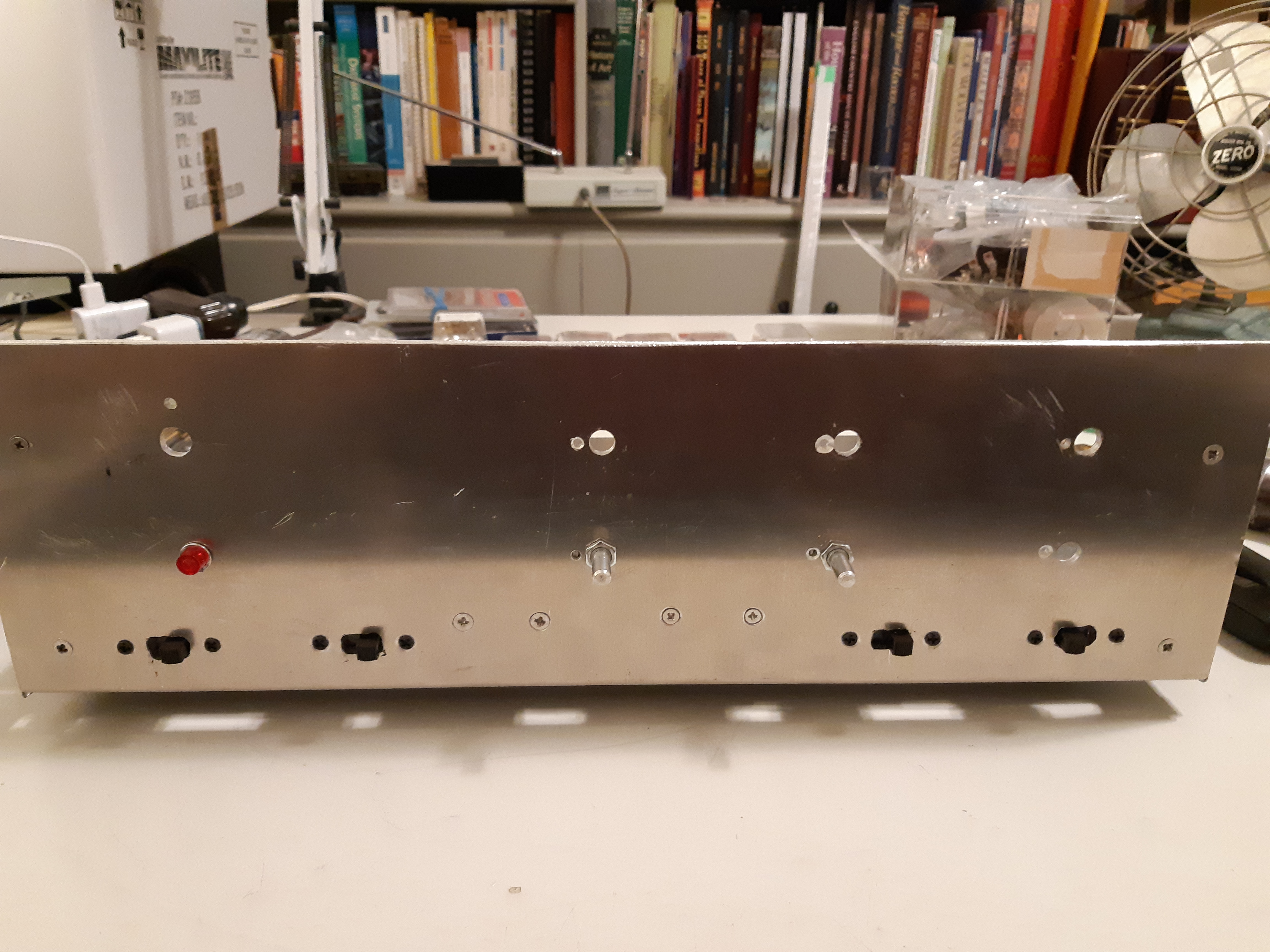
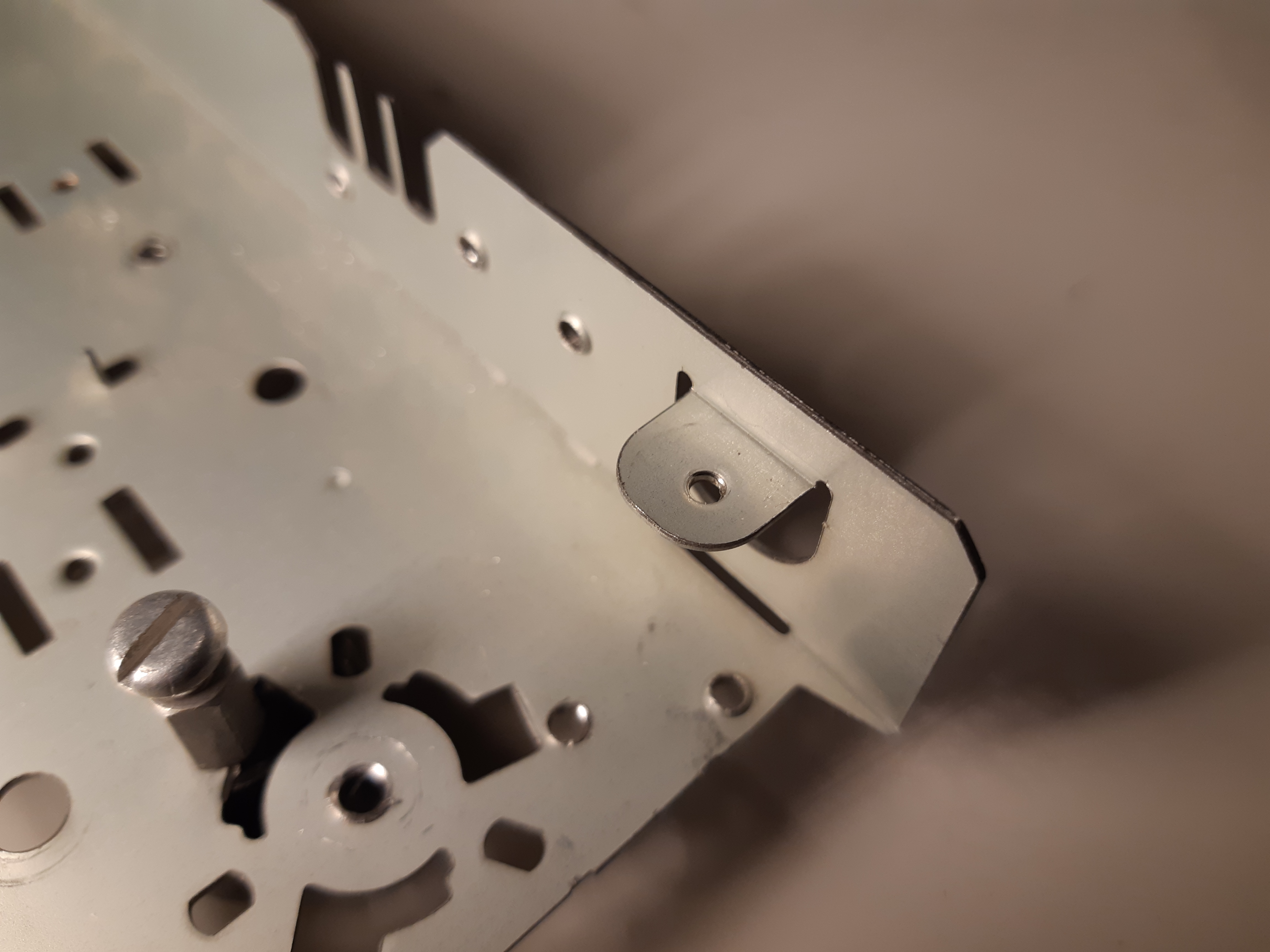
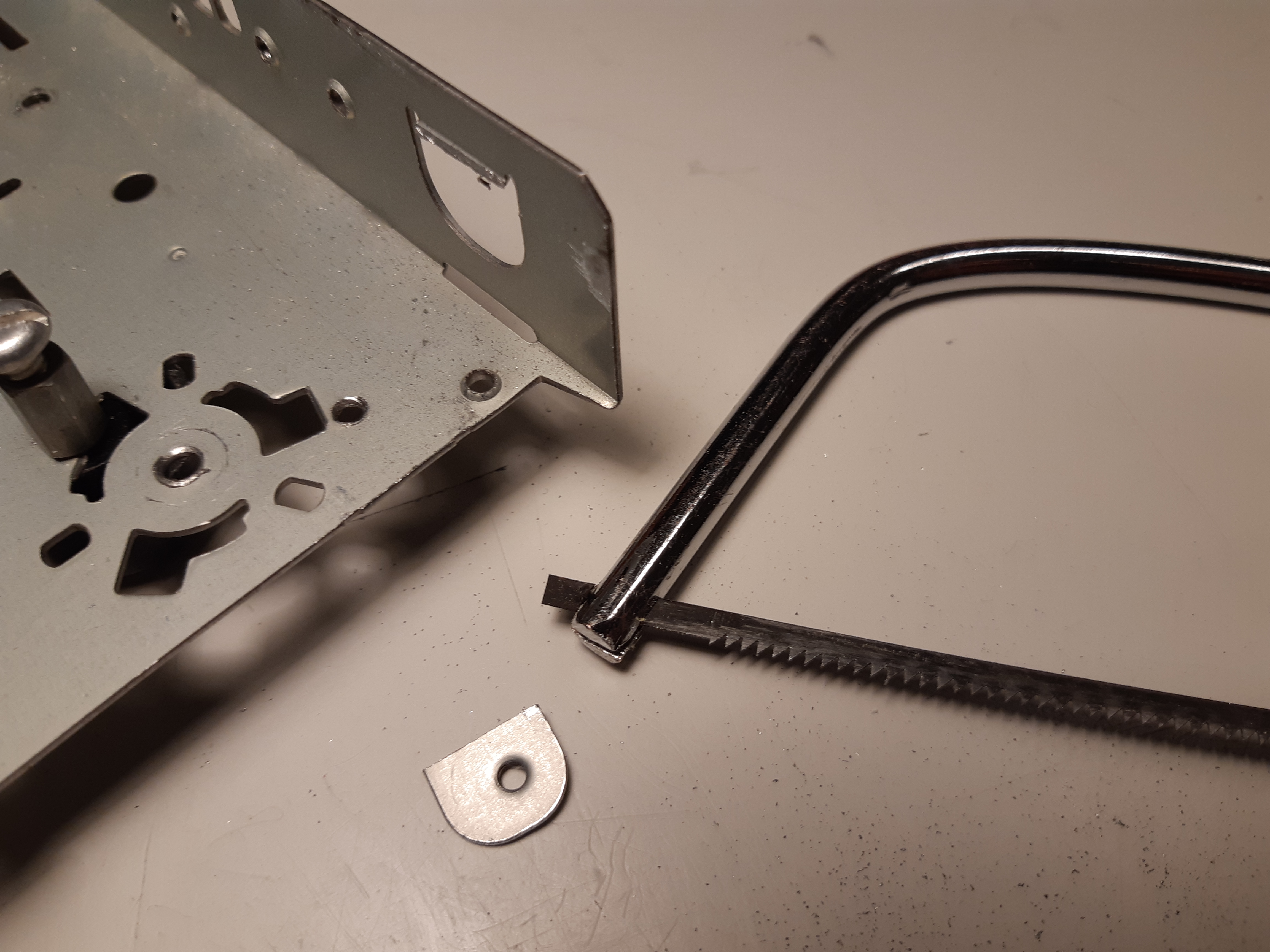
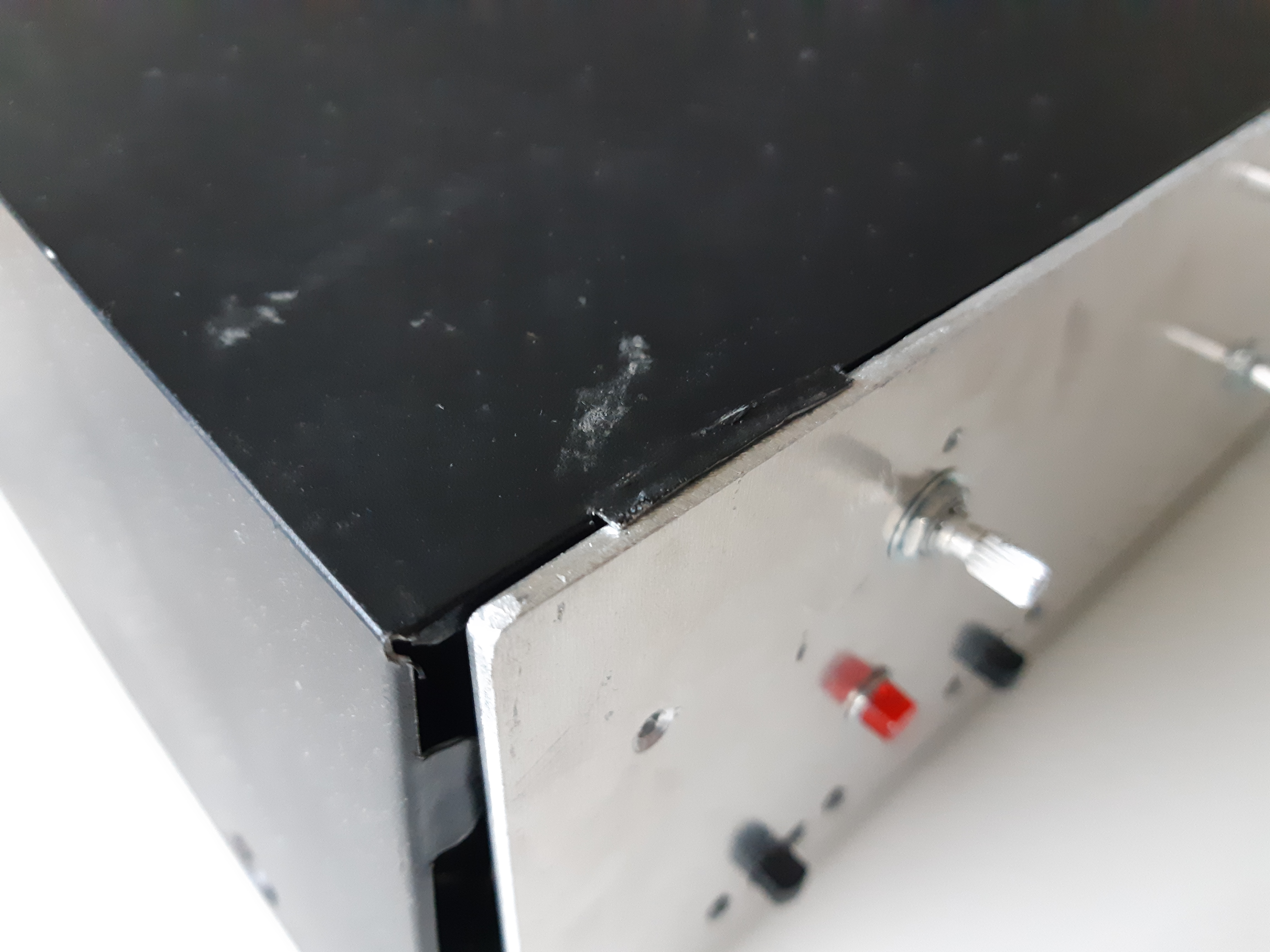
The rear panel and front subpanel were put back together. Then, I ran into a problem that I had apparently overlooked while trying to put the top cover on: the front edge of the cover had nothing to rest on (fig. 99).
Images below show how supporting tabs were cut for the front top section:
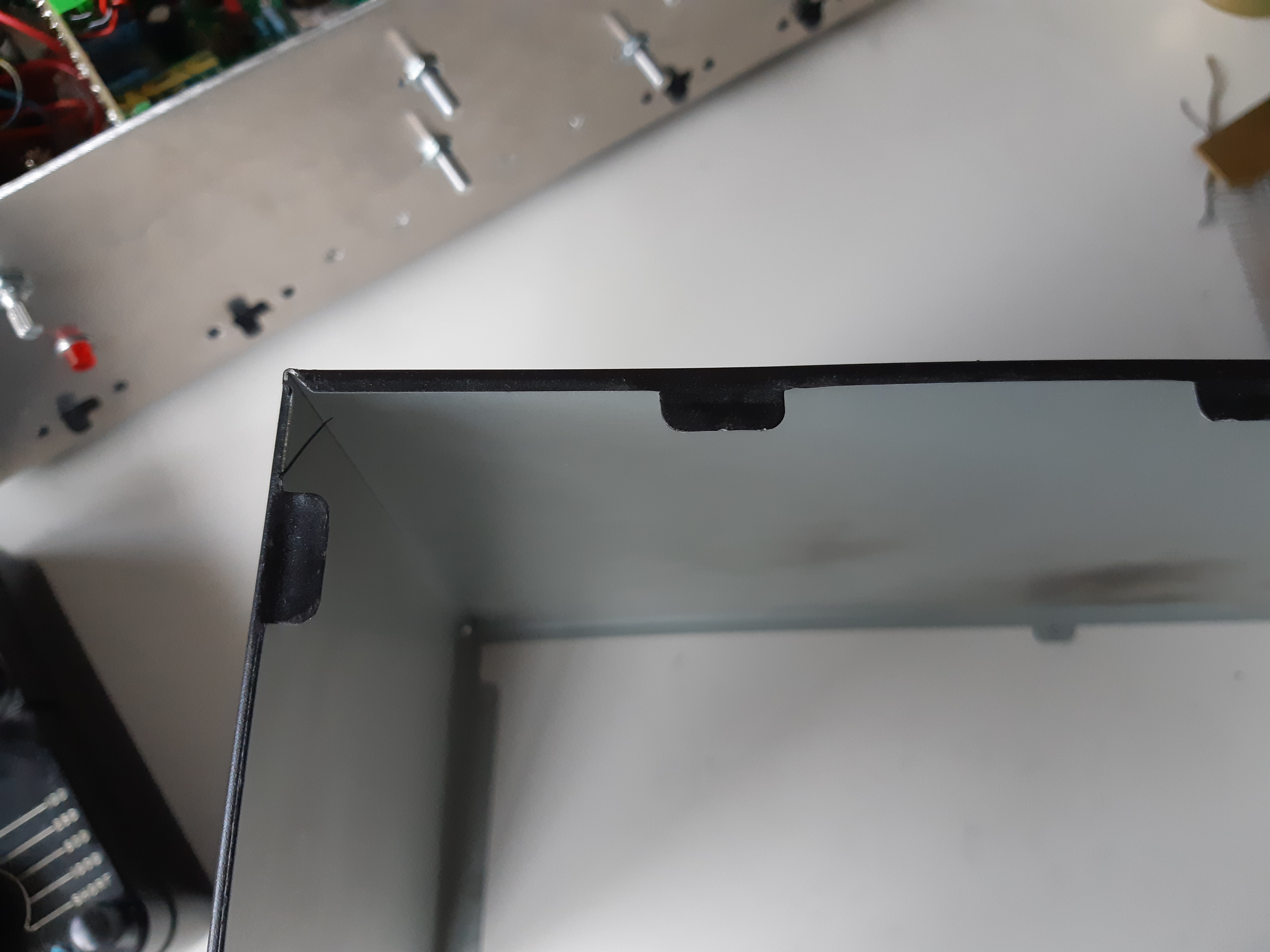
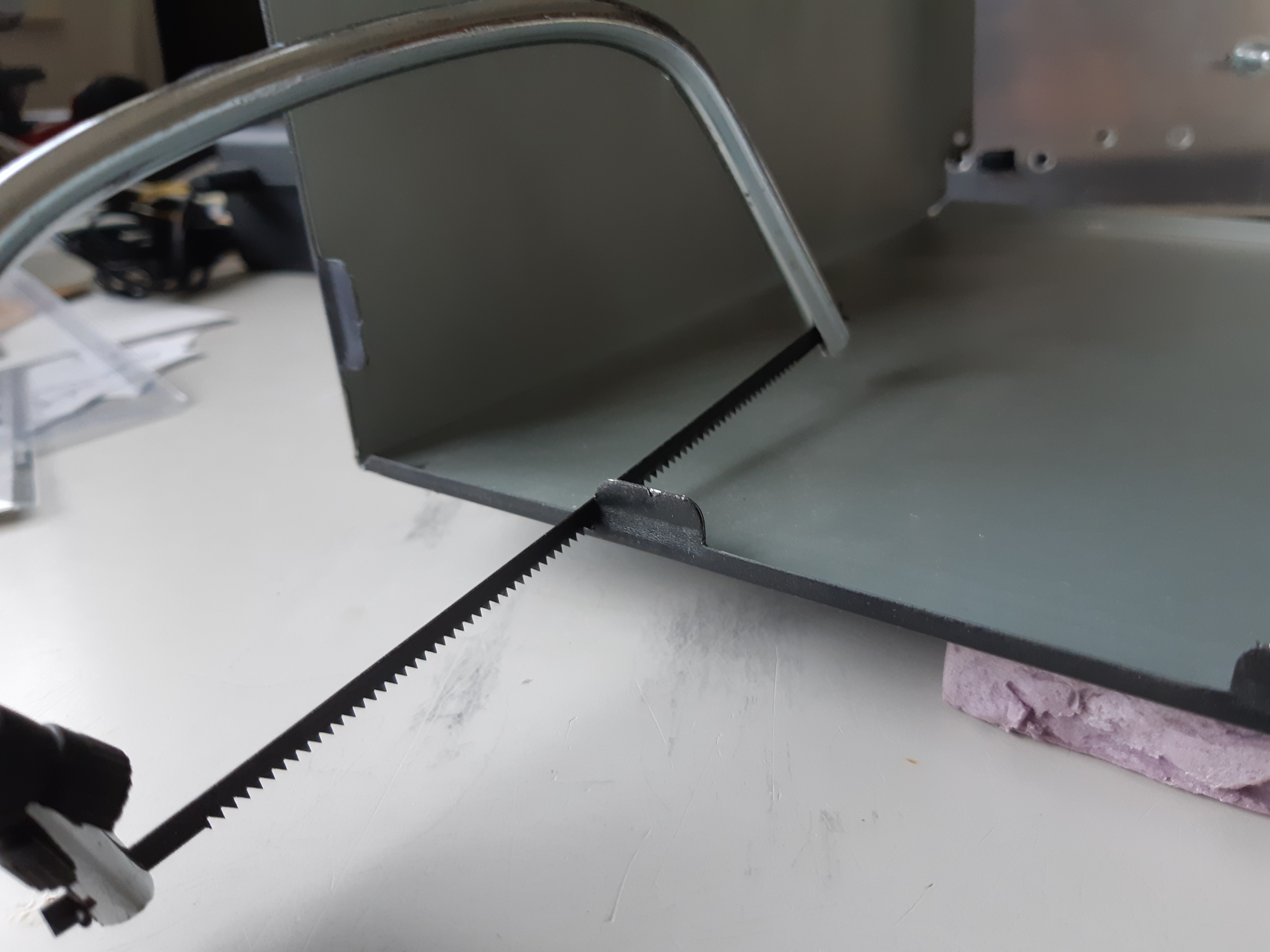
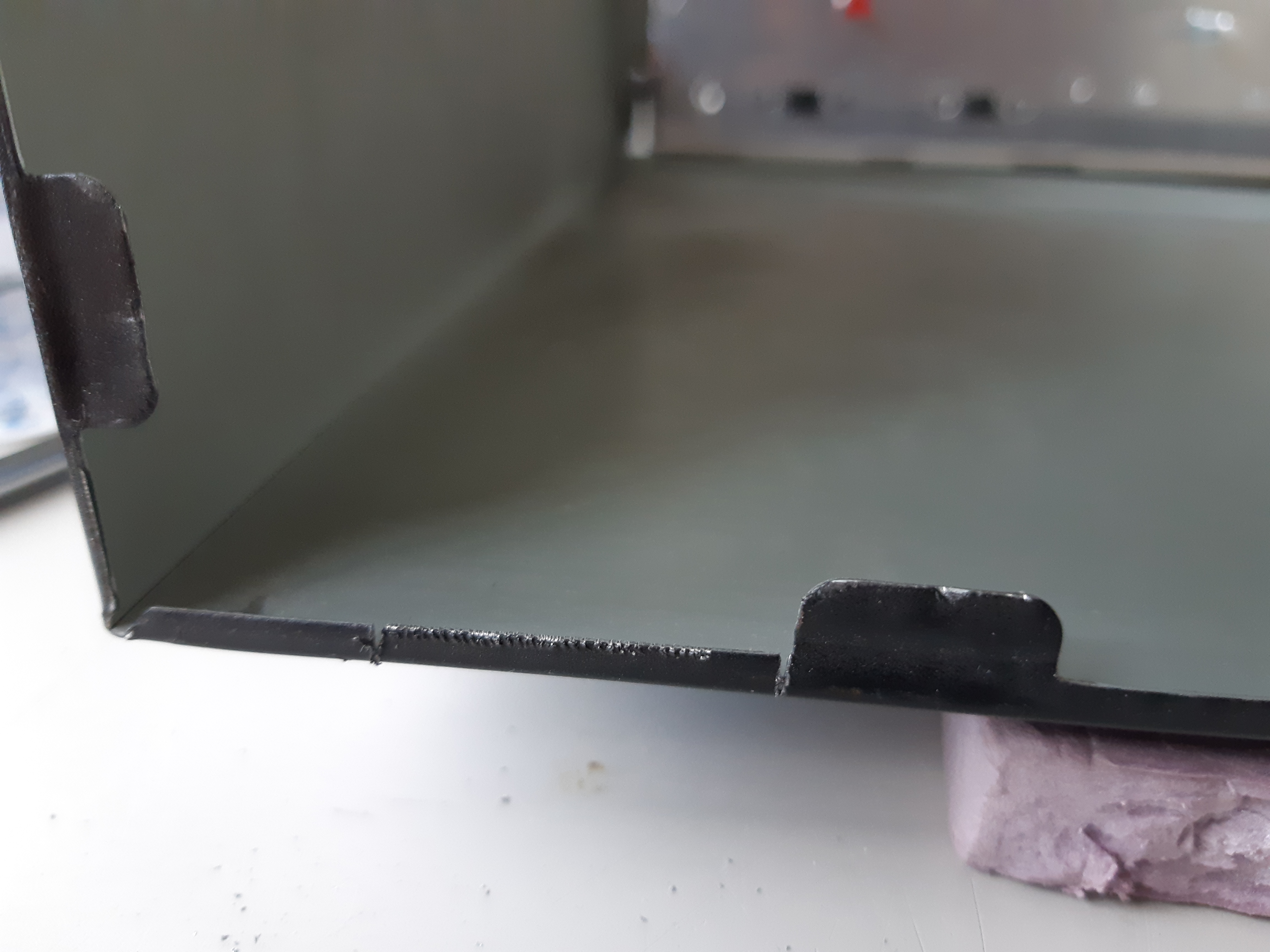
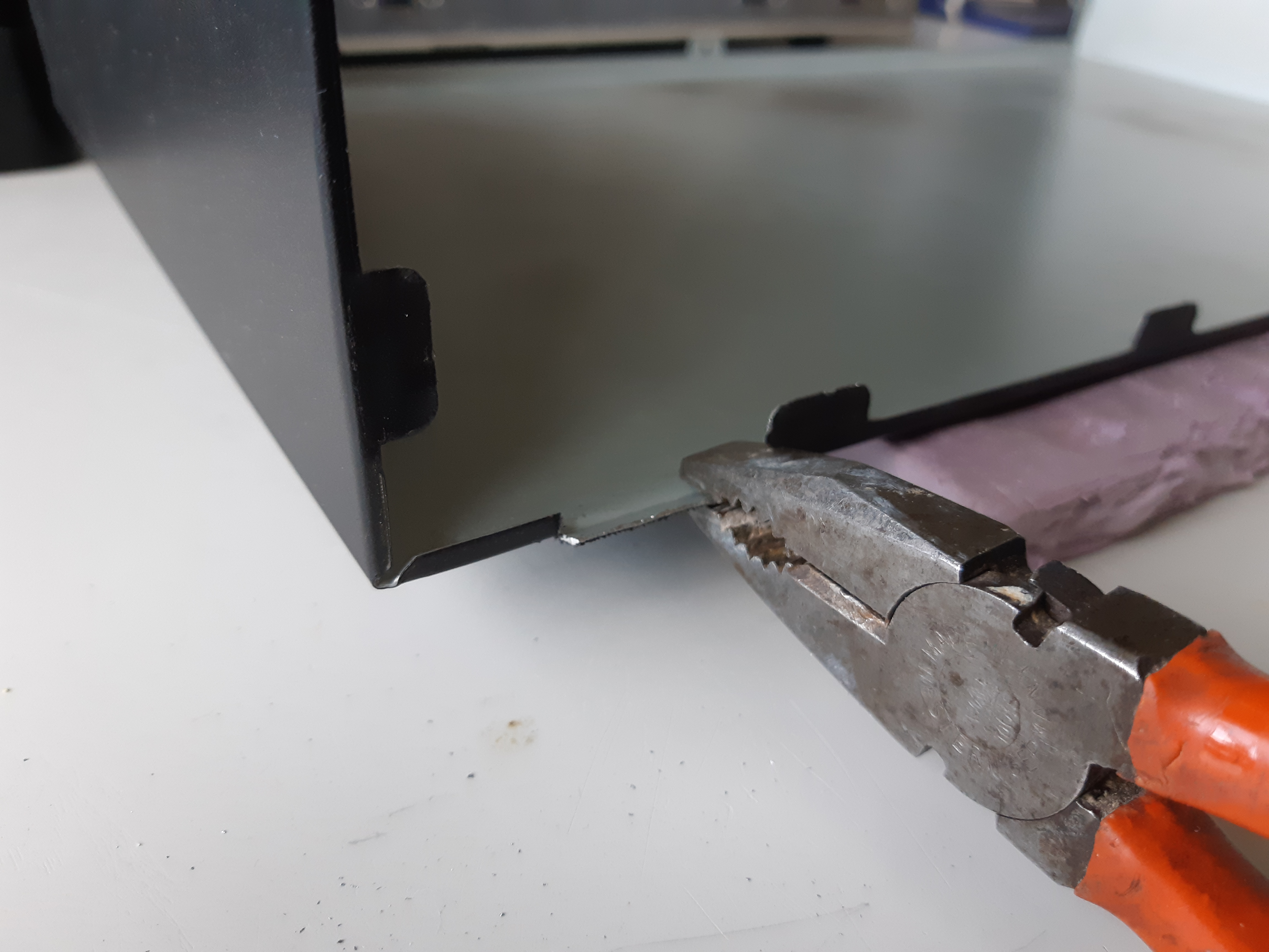

The cover can now close properly (fig. 100):
Initial Tests
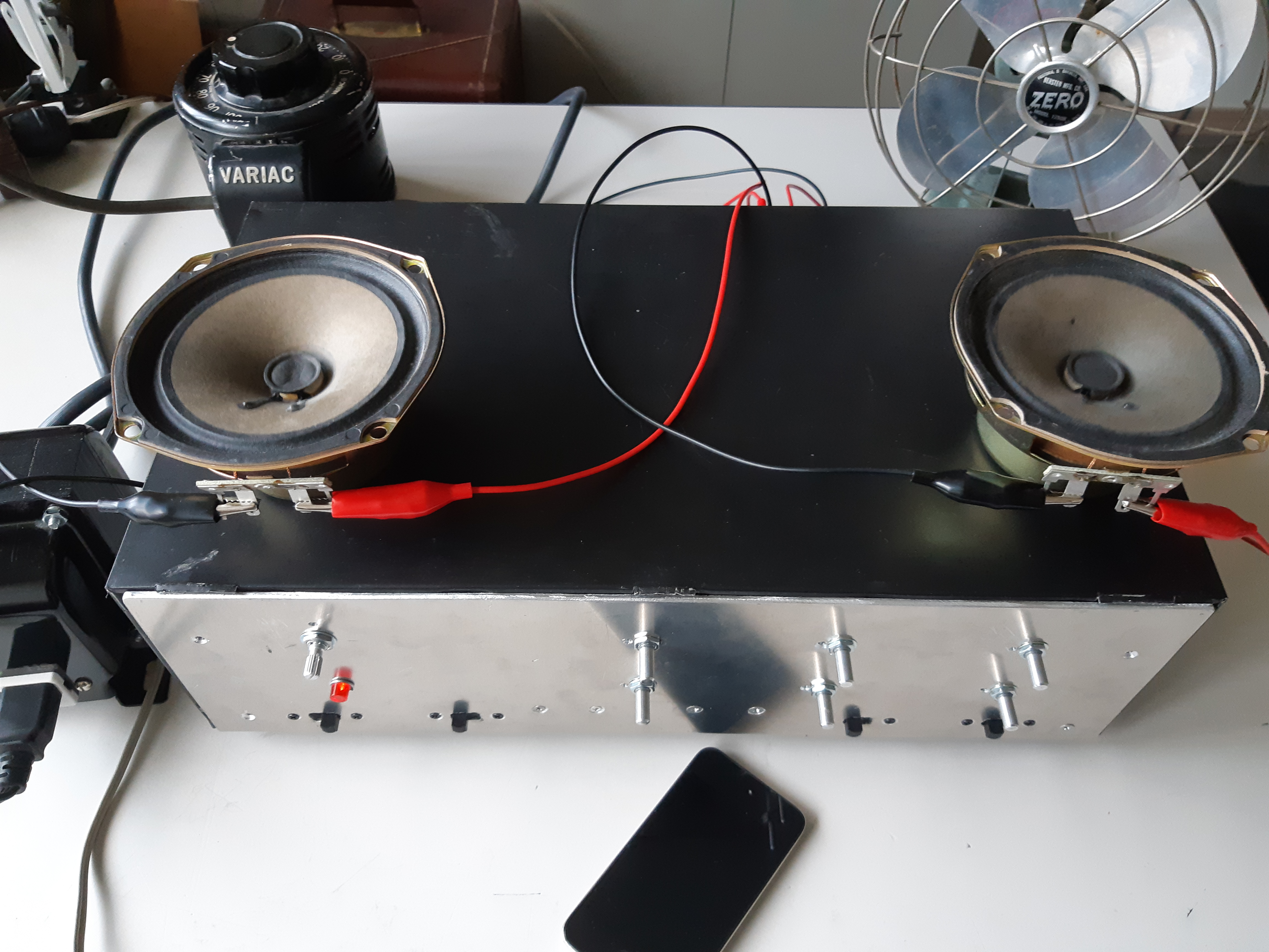
With internal components and modules hooked up and double checked against the diagram at figure 91, and the case reassembled, the set was now ready for testing. An audio source was connected to one of the “AUX” channels (I used an iPod as the audio source), and a small pair of speakers salvaged from a junked television set were hooked up (if powering up for the first time, make sure the set works properly before connecting to a “good” set of speakers). A power cable was attached and plugged into an isolation transformer which in turn, was plugged into a Variac (variable voltage auto-transformer). Note: If possible, avoid plugging directly into AC mains thing on which you are working; use an isolation transformer with a Variac instead.
With the set switched on, volume turn down, and Variac starting at zero volts, the AC line voltage was slowly turned up, keeping an eye and nose open and on alert for any “magic smoke” or fireworks. When I got up to full line voltage of 120 volts without any problems whatsoever, I could hear a hum in the speakers as I gave a minute for the tubes to warm up (because this is a transistor-tube hybrid set with the output stage being solid state, there will be, at the very least, some subtle noise in the speakers immediately as the set is turned on).
After a minute, I turned the volume up and heard nothing but a buzz. So, I checked the iPod and it was playing. Then I turned the volume up to full and could barely hear the audio from the iPod. My heart sank…after all this work, it’s not working??? After a moment, it suddenly dawned on me that the selector could be on the wrong channel. Turing the volume back down, I gave the selector knob a turn and the music finally came on. The new stereo system was working!
However, there was still a problem with a loud hum. The first thing I noticed was a poor connection between ground side of the audio input and common negative of the set. Soldering a wire to the ground tab of the RCA input jacks and hooking it up to one of the screws on the chassis reduced the hum substantially, but the remaining hum was still pretty loud; so it must be coming from multiple sources.
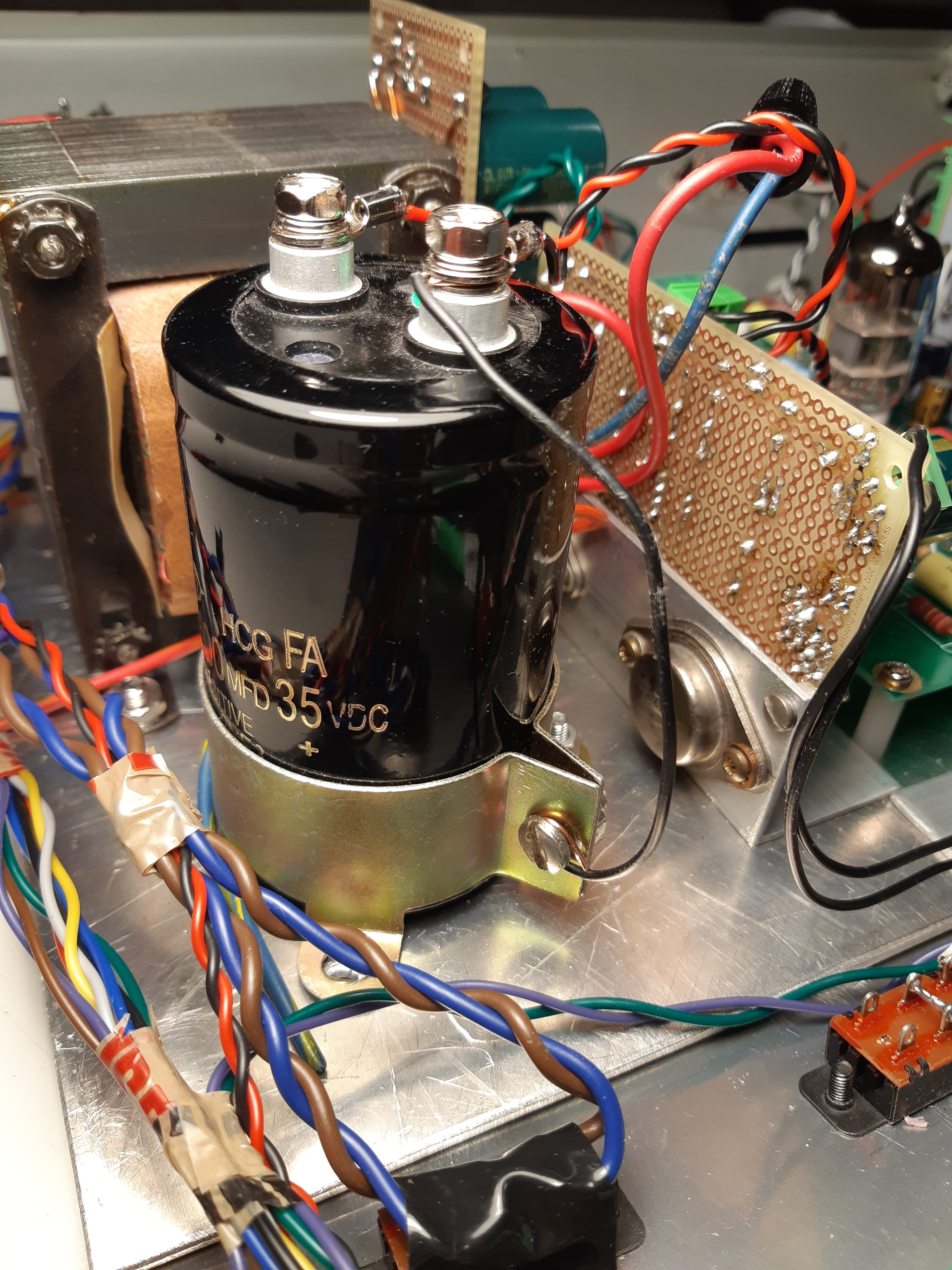
As negative of the 300 volt and low voltages lines were all connected to the chassis as common ground, the source was hard to find but by chance, I discovered that when I place my finger on the negative terminal of the large 100,000μF (0.1F) filter capacitor, the hum was further reduced. Despite the negative already connected to the chassis ground, more grounding points were needed as the lines were picking up noise. A wire was connected from the negative terminal of the large capacitor to a screw on its holder ring and the amp was quiet (fig. 101). There was still a subtle hum but it was tolerable.
WARNING: If using a finger as a probe (which I do NOT recommend), keep one hand in your pocket and/or behind your back away from the set. Because the negative side of the 300 volt line shares the same common ground with the negative of the low voltage power and signal lines, contact with the positive side of the 300 volt supply can cause a painful or even fatal shock if any part of your body is in contact with the chassis or any grounding point.
The Icing on the Cake
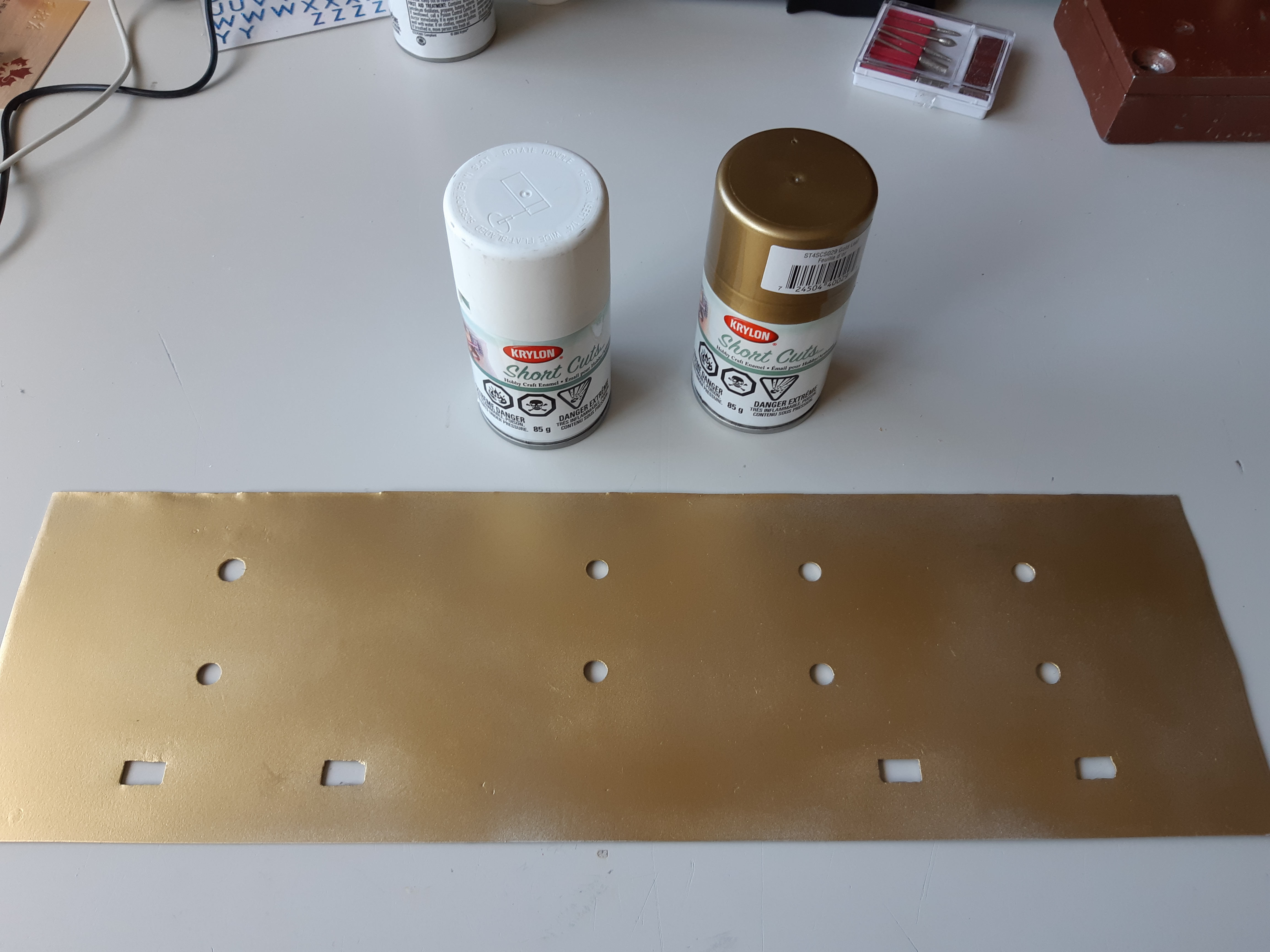
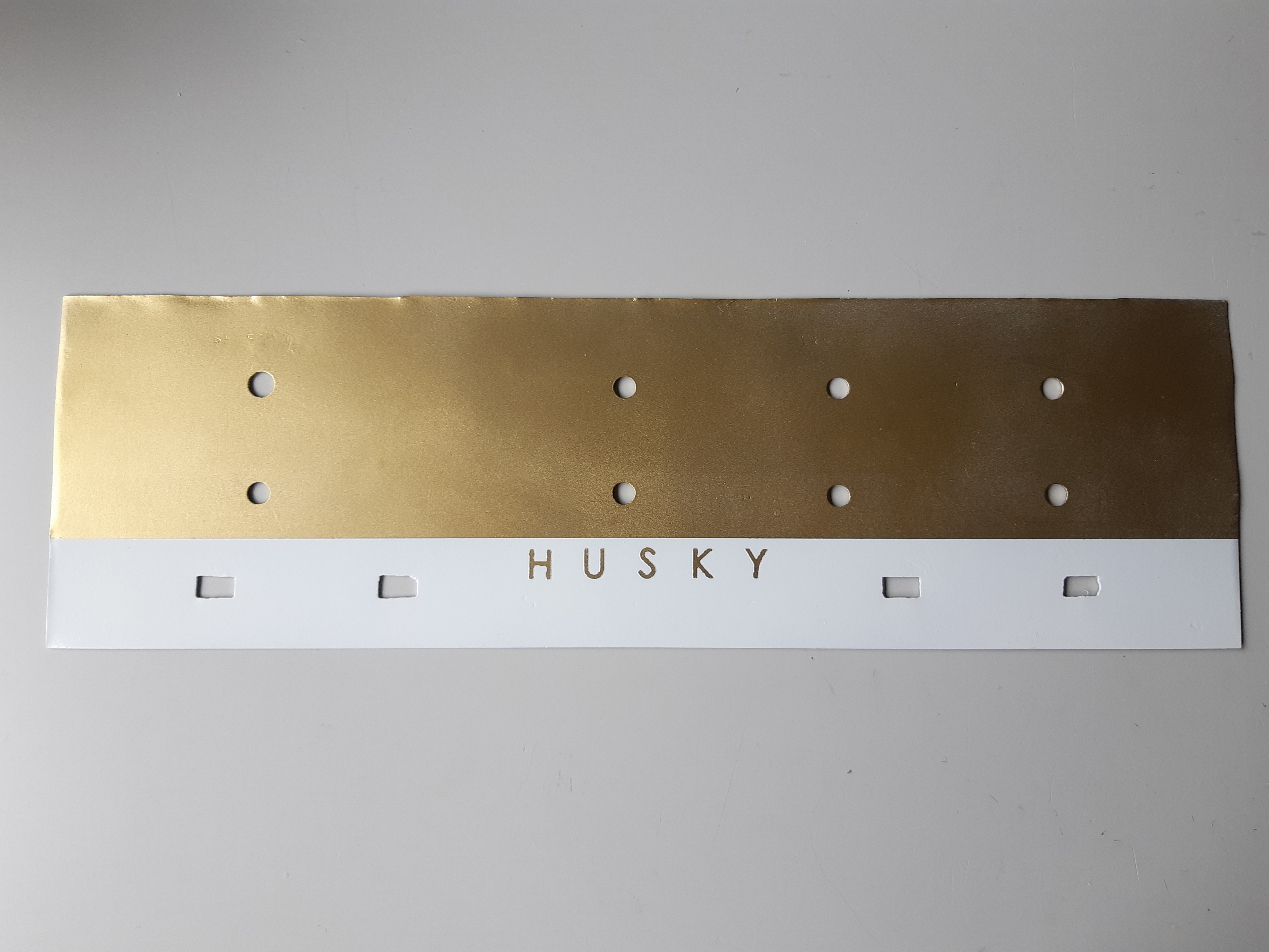
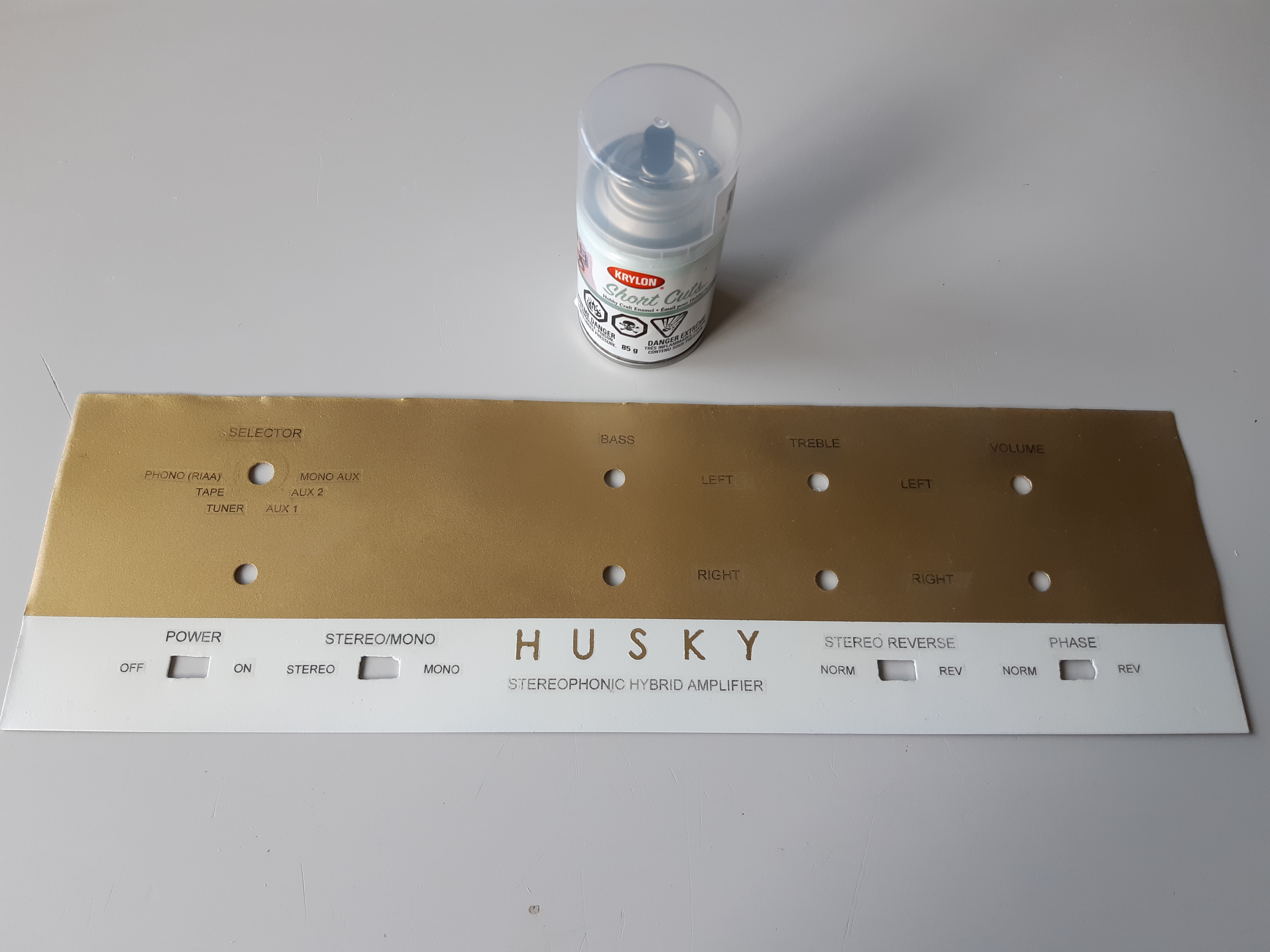
With the set fully functional as expected, all that’s left to do was to finish the front panel (the piece that goes over the subpanel). To re-create the two tone look, the panel will be spray painted with white and gold Krylon spray paints. The large letters (“HUSKY”) will be reverse stenciled while printed decals were used to label the knobs and switches.
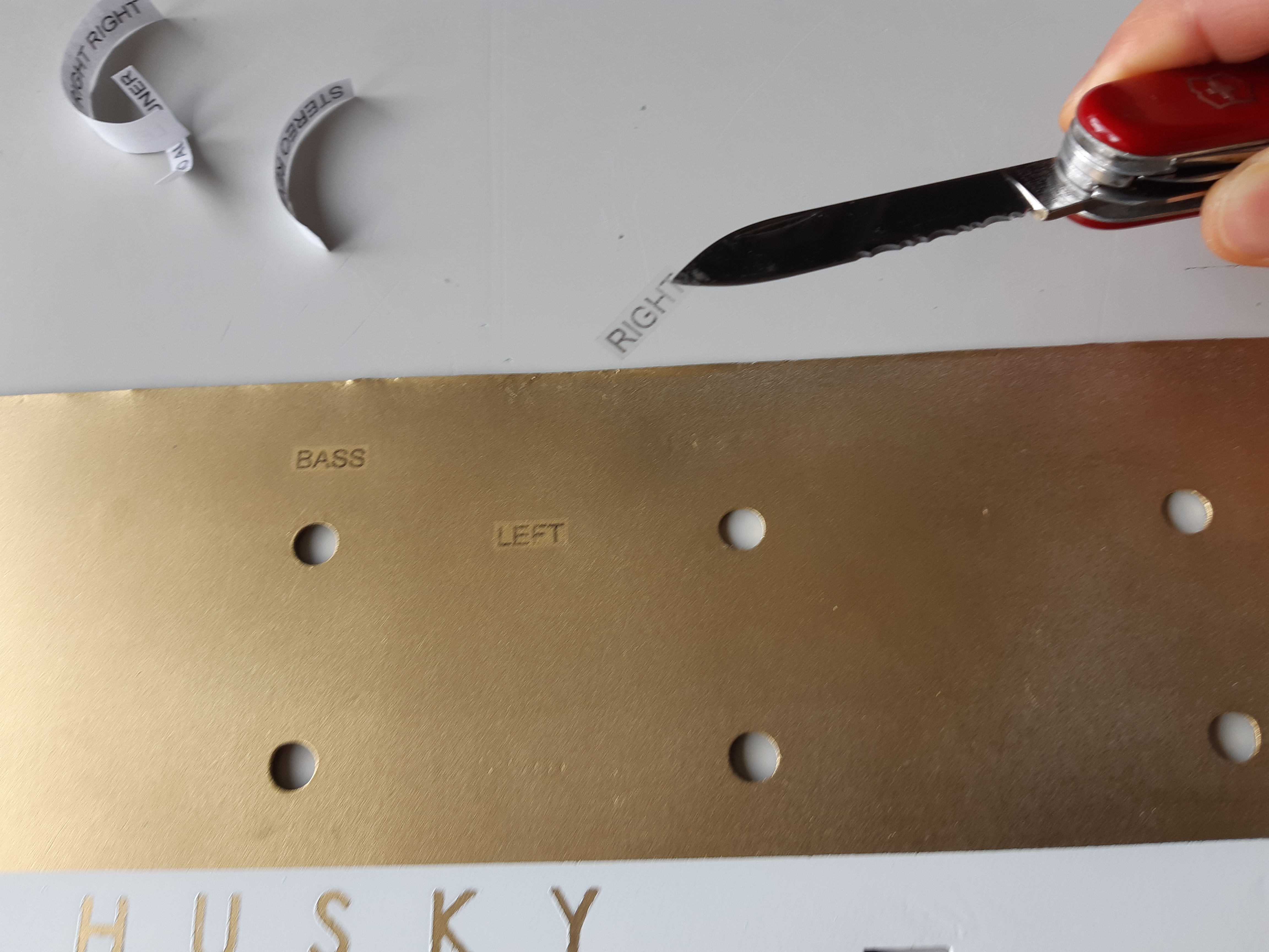
In preparation for spray painting, the filled holes were scrubbed with steel wool to ensure a continuous smooth surface. Then, the entire surface was cleaned with rubbing alcohol to remove fingerprints and dirt. The surface was then sprayed completely with Krylon flat white as a primer with about three layers in order to cover completely. The entire flat white surface was then covered with three layers of gold paint (fig. 102).
When the paint had dried, letter stickers, used as reverse stencils, forming the word “HUSKY” was placed along the lower portion of the front panel (fig. 103). To position the letters, a vertical was gently marked with a pencil down the center where the “S” would be placed. A couple of vertical lines 0.75″ (3/4″) apart were marked to the left and right of the center line. A horizontal line 1″ from the bottom edged was marked as a guide line.
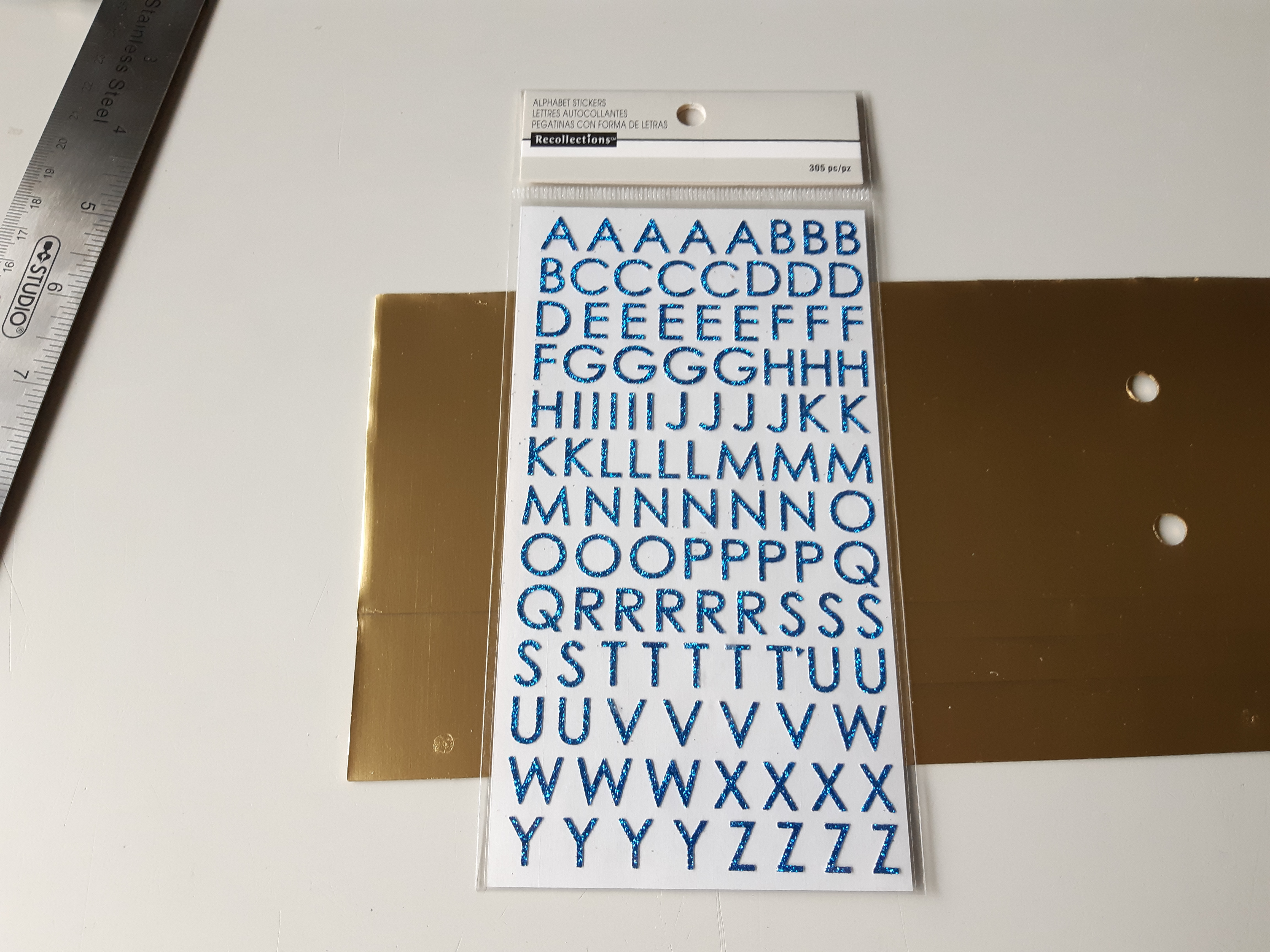
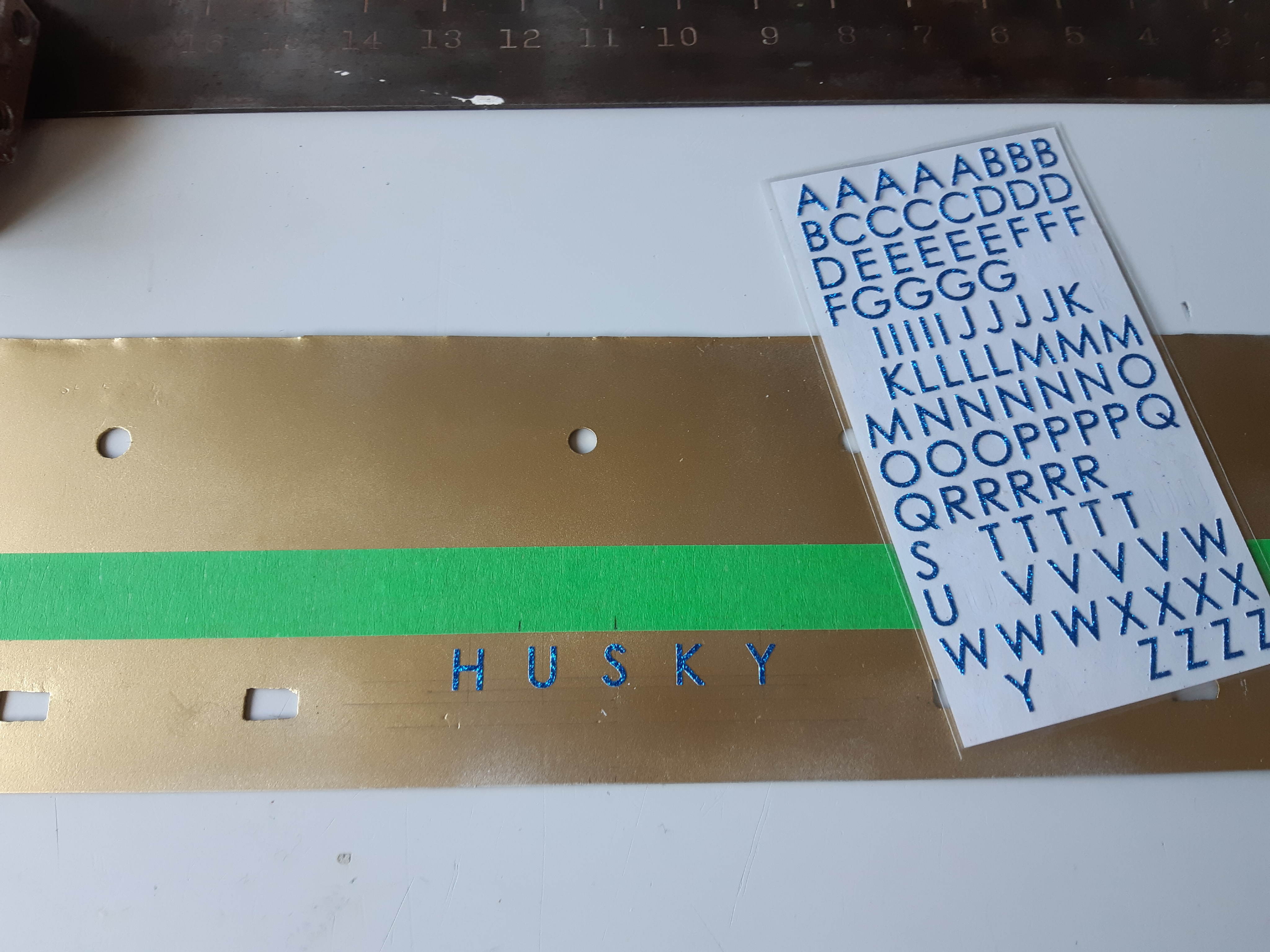
Using the markings as a guide, letter stickers were then placed along the lower panel so that bottom of the letters barely touch the horizontal line while the vertical center of the letters align with the vertical lines (fig. 103).
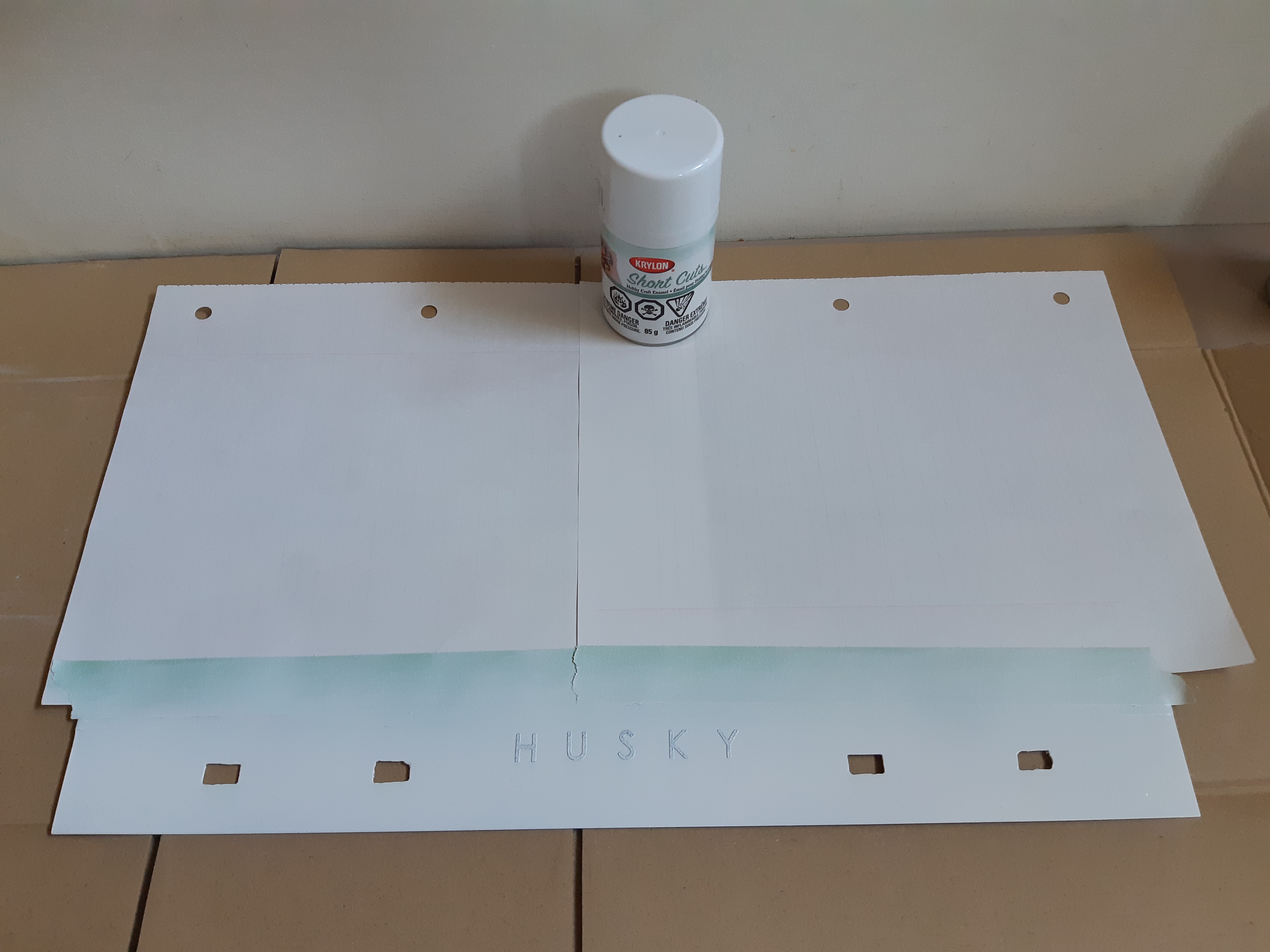
Masking tape was placed across the panel forming a border line 1.5″ from the bottom, and the upper portion was covered with paper while the lower portion was exposed, which was then sprayed with a few layers of white gloss paint (fig. 104). When the final coat had dried, the paper covering the upper part and masking tape were removed. The letters stickers, now coated with white paint, were also removed, exposing the gold paint underneath and appearing as gold font (fig. 105).
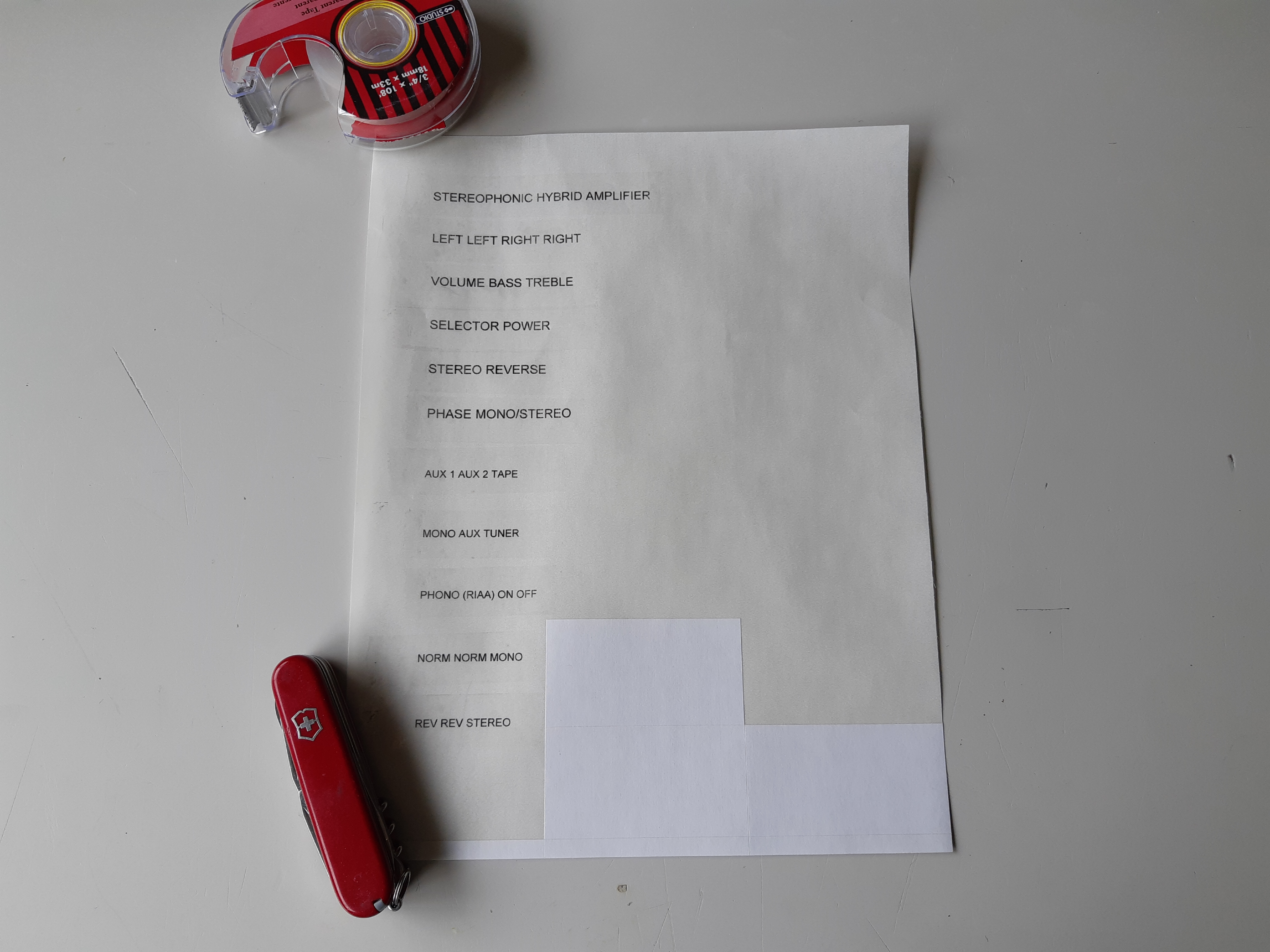
As the project approaches completion, the next step to was to label the knob and switches. By this time, it was early August 2019. Though the project was started in April 2018 (and went hiatus for several months before starting again in July 2019), it took awhile to come up with a way to make the labels. Rub-on dry transfer such as Letraset was not an option as they are now hard to find and letters tend to fall off rather easily. I have looked into engraving as well but the process either has a high set-up cost and/or the panel was too big to fit the engraving machines. After posting in an online forum, a member suggested toner decals.
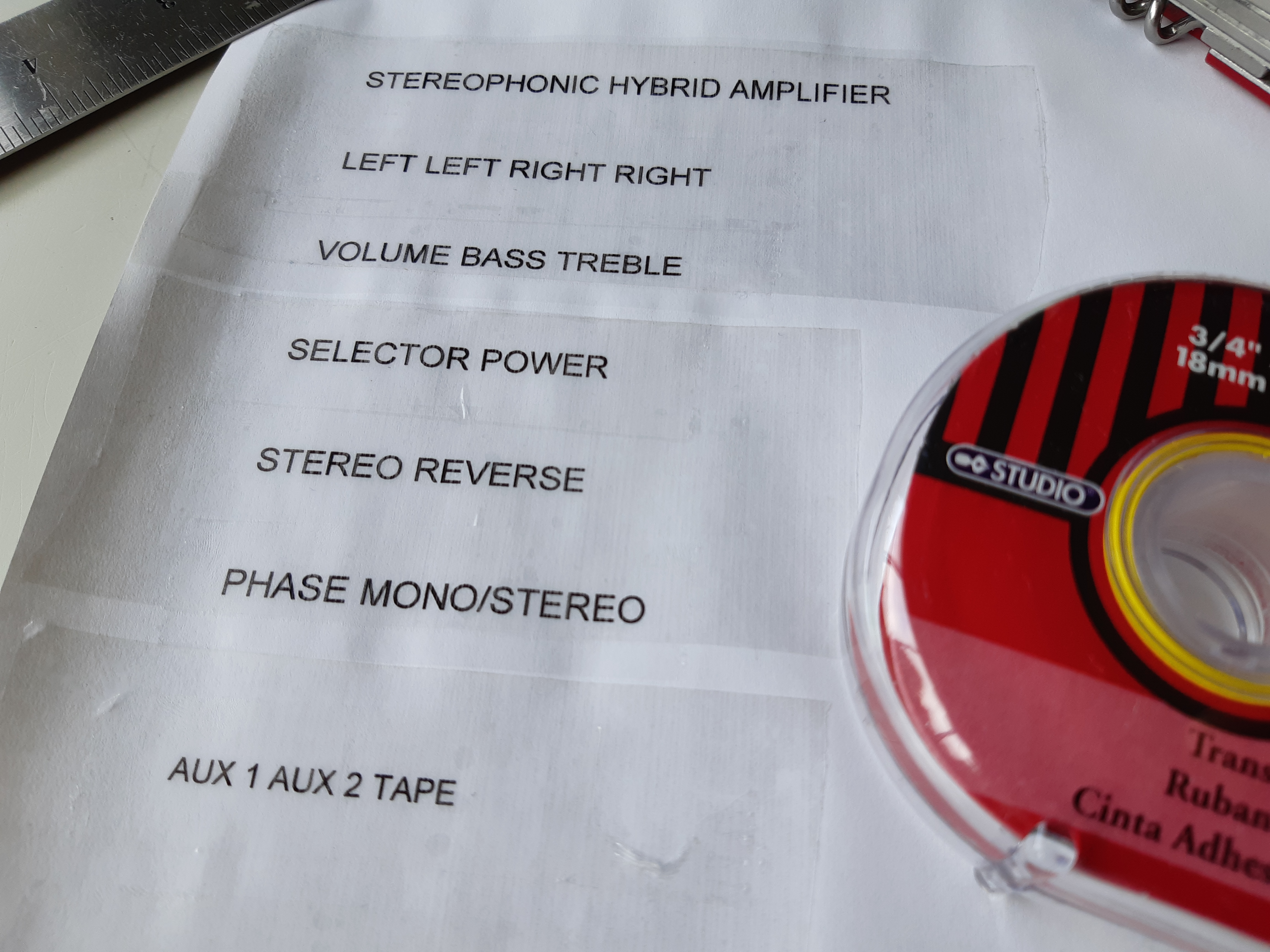
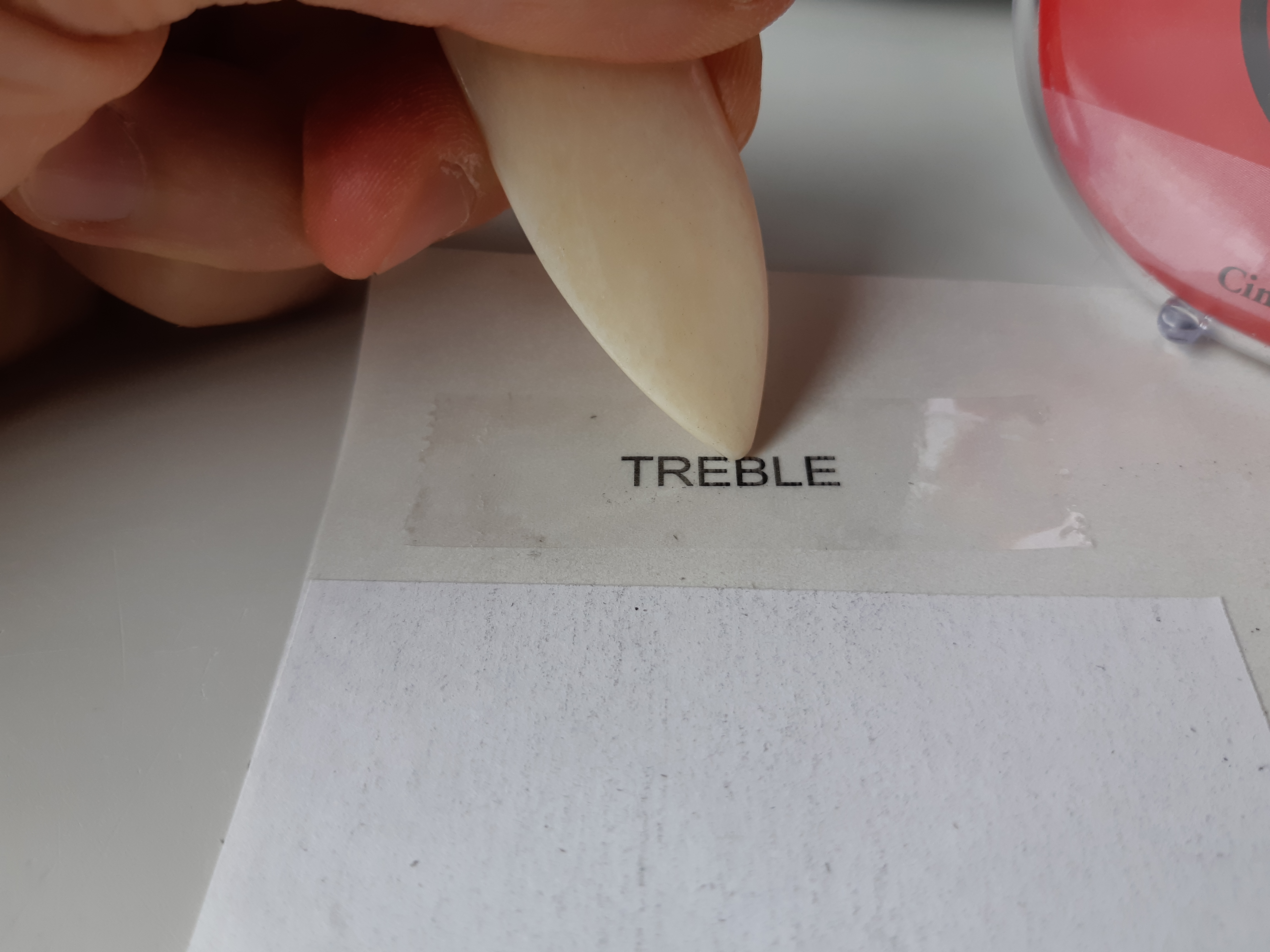
To make a transferable to toner prints, letters were printed onto a sheet of adhesive backing (with stickers removed) with a laser printer (fig. 106). Transparent tape was then placed over the letters (fig. 107) and rubbed with a bone folder (fig. 108). Labels were then cut out (fig. 109), backing peeled (fig. 110), and carefully placed on the panel at the appropriate spots. With the decals in place, a few coats of Krylon clear gloss was sprayed over top to protect the paint from scratching and labels from peeling (fig. 111).
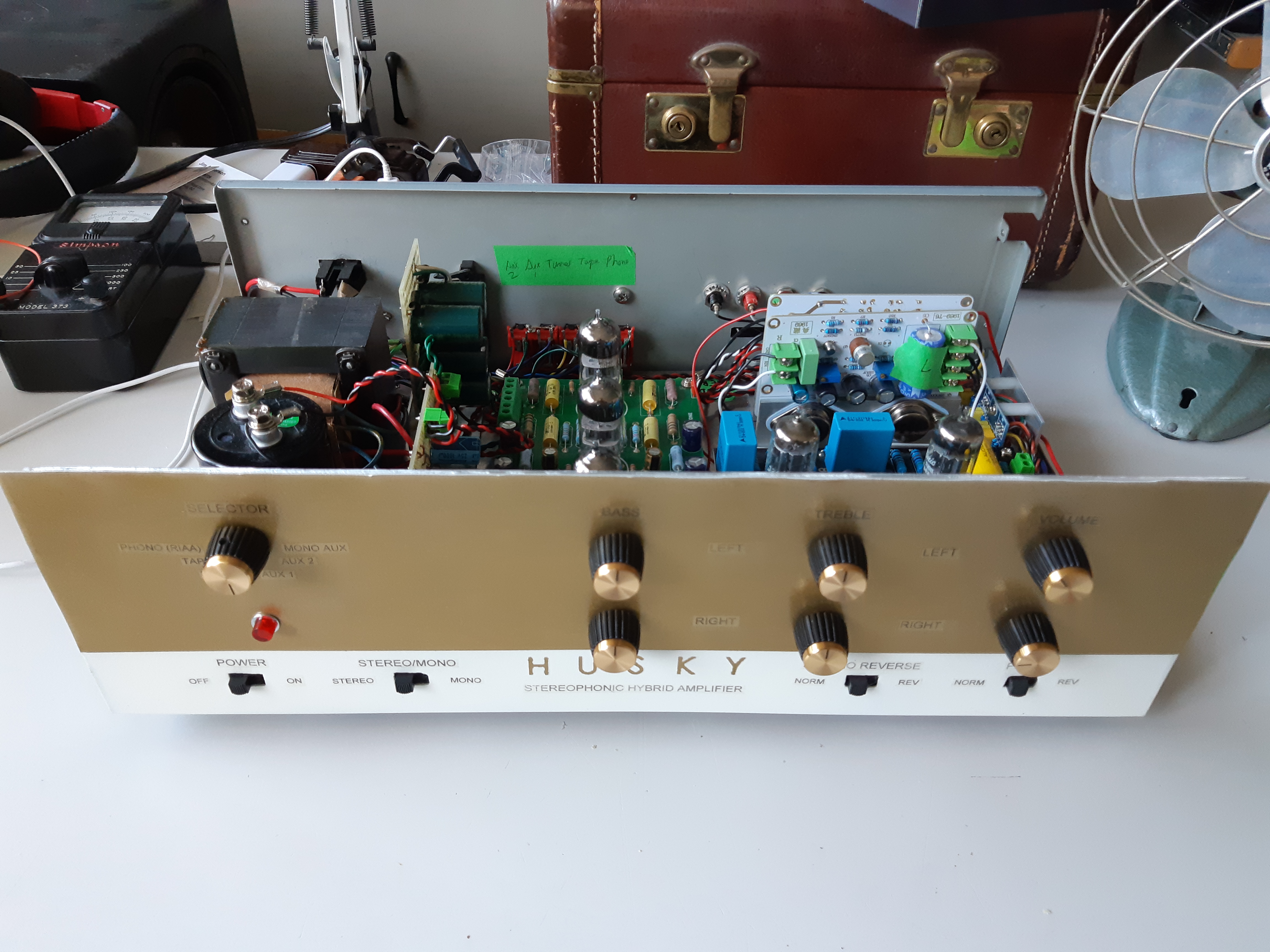
When the final clear coat dried, the front panel was placed over the subpanel and held in place by the nuts of the pots and rotary switch. Marshall replacement knobs (for Marshall guitar amps, these knobs were most likely knockoffs but it didn’t really matter in this case as the black and gold matched the front rather nicely) were then installed over the pots and rotary switch.
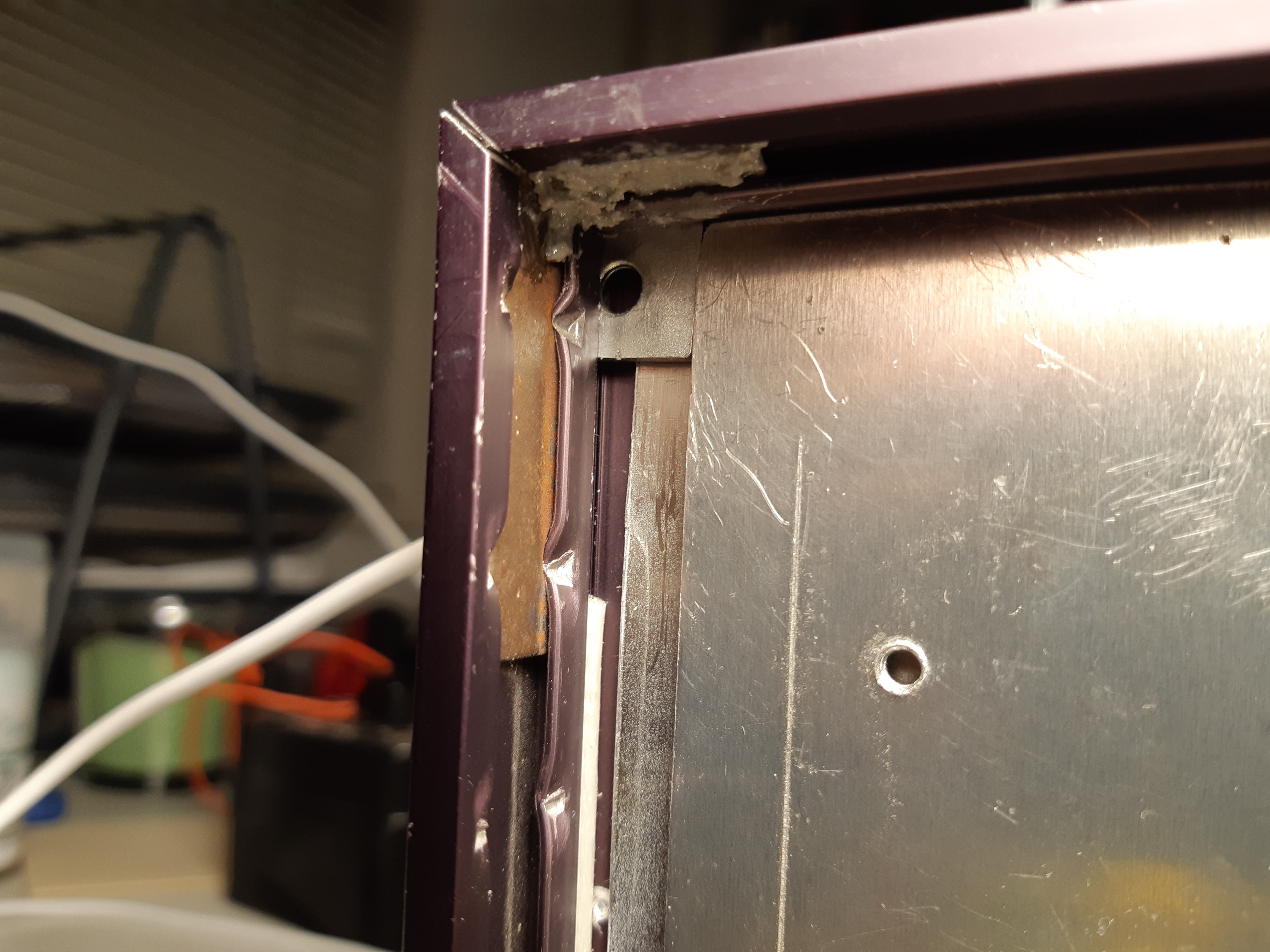
The final step was to install and secure the resized picture frame around the front panel. There were a few challenges here: the frame can not be held in place with screws (nothing to screw into), the finished front panel must not be drilled (in order to keep it neat and clean) and with frame in place, it must allow for easy removal/replacement of the top cover.
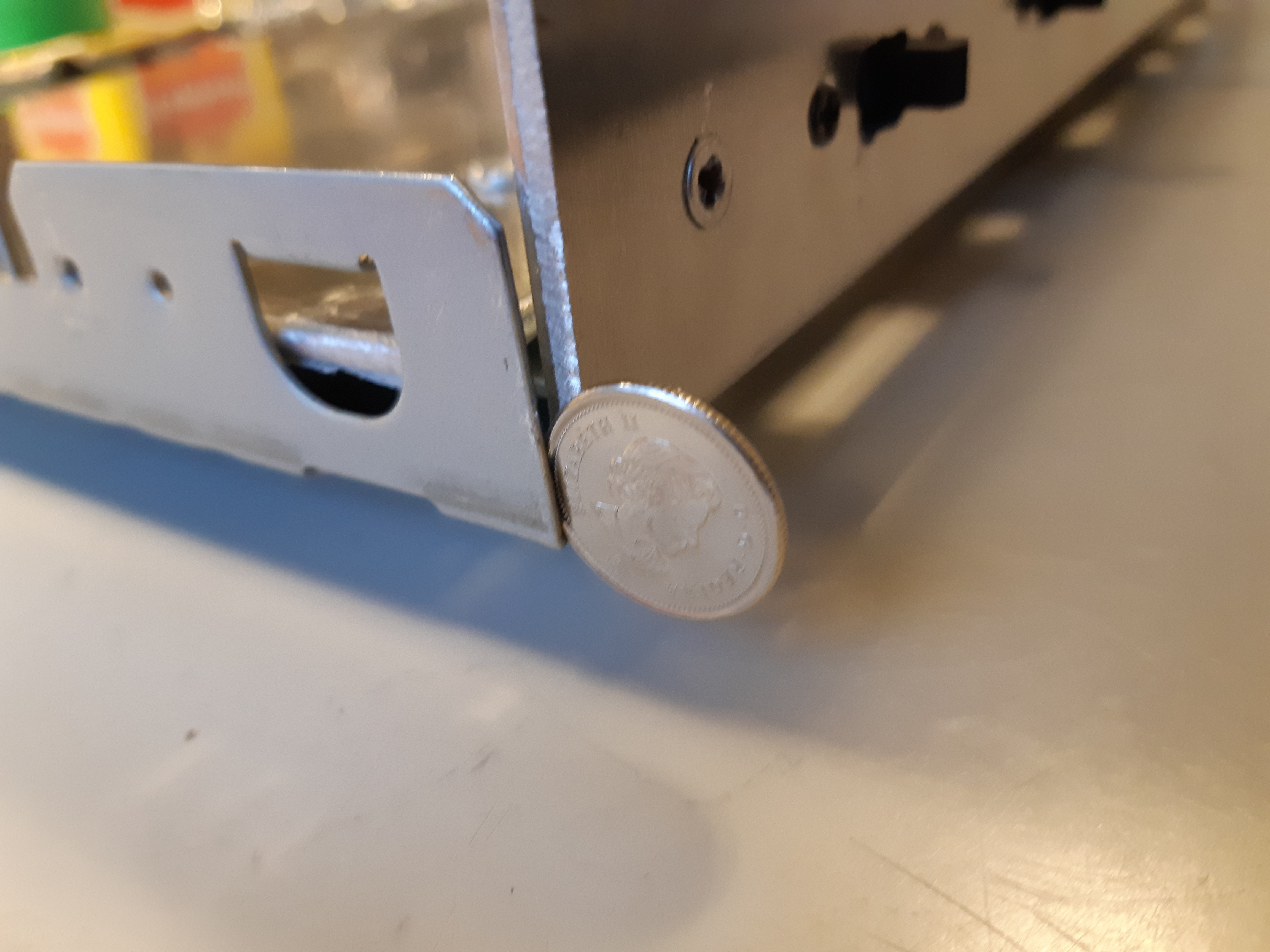
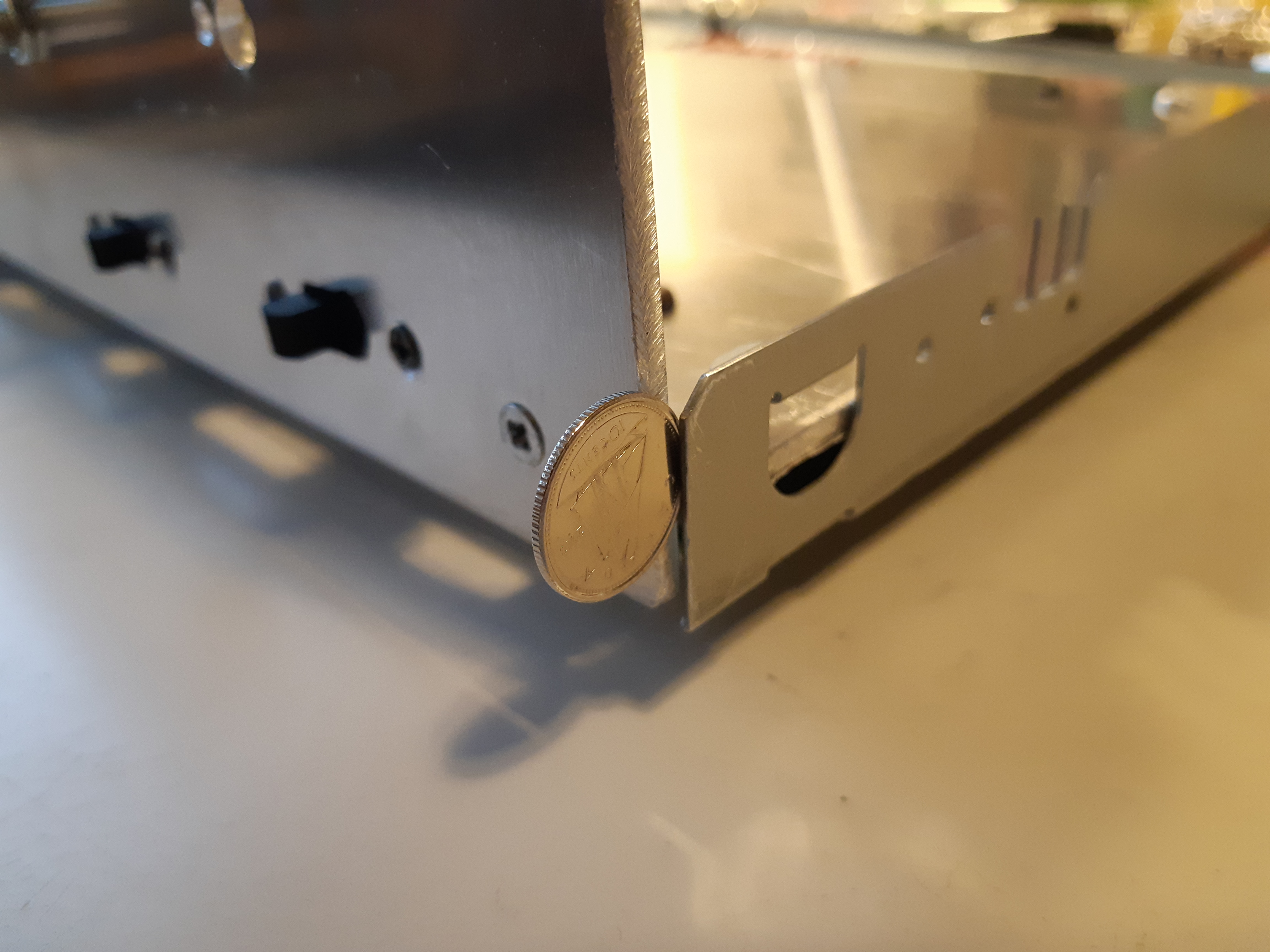
Looking at the inside of the frame, I noticed a groove filled with silicone rubber at the level where the glass normally goes (originally used to cushion the glass) and realized I could wedge something in the corners, securing the frame to the outer panel. This would allow for easy removal of the frame should I wish to re-do the panel in the future. So first, the silicone rubber in the groove at the corners were removed (fig. 112) and the frame was placed around the front to check for require thickness and size of wedge piece. A nickel (5 cent coin) was of the right thickness but too big to fit in the space between the subpanel and inside of the groove. Looking around my spare parts box, I found a couple of small angle brackets (same as the ones used to put the frame together). Because these were of the right thickness, small squares were cut from the brackets (fig. 114) and wedged into the corners, holding the frame in place (fig. 115).
Using the Amplifier
The newly completed amplifier was now ready to be given a listen. A pair of stereo speakers were connected to the output terminals and an iPod was used as a music source (note: the correct way to use an iPod with a stereo system is to connect using a LINE LEVEL adapter via the data/charging port on iPod, NOT the headphone output jack). With treble and bass controls set to 12:00 position, left and right volume turned down, and switches set to normal positions, the set was powered up and given a minute for the tubes to warm up.
The left and right volume were turned up. To adjust for balance, the stereo reverse switch was switched back and forth while adjusting the volume knobs until difference between normal and reversed stereo was hard to hear (some may prefer to use the phase switch to help adjust the balance).
In the video below, are a couple of demonstrations (I have included two videos with different sound content in case one is blocked in one’s country and the reader does not have access to a VPN). As the demos were recorded with a phone, audio of the videos do NOT do it justice. Music: “Dancing in the Silence” by Joe Edmonds (first video) and “Shooting Star” by Bag Raiders (second video).
The sound was indeed warm like a classic tube amp should sound, with a strong in-tune bass and smooth clear highs. Not all MP3 files sounded good as the amp revealed the limitations of compressed digital audio (yes, there can be such a thing as “too good”). Later, I auditioned the amp again with a CD player and what I heard was unbelievable: the amp made CD’s sound like vinyl records!
If you have a system with a similar preamp module with 12AX7/12AU7, you can try swapping the tubes around for a different sound. Other tubes from the 12AX7 family you may wish to try are the 12AT7, 12AV7 and 12AY7. As they have different gains, one of the first things you will notice is the different “feel” of the volume control in addition to sonic differences.
In this particular set up, I have found the best preamp tubes to be an old Russian/Soviet 6Н2П (written as 6N2P in English), a dual triode with similar characteristics to that of a 12AX7 but with a 6.3 volt filament. In order to use the 6N2P safely, the filament line was disconnected from the amp’s built-in 12.6 volt power supply and was connected temporarily to an external DC power supply set to 6.3 volts. If I had known about the 6N2P earlier, I would have designed the filament supply for 6.3 volts instead of 12.6 volts. Overall, the sound was even better with the 6N2P’s in place of the 12AX7 and 12AU7; however, MP3’s continued to show their limitations. Compressed audio is really meant to be played with BPC systems after all.
And speaking of “HUSKY”, we are looking into welcoming a husky puppy soon and will have very little time for projects. As of this writing (August 21, 2019), I have one current on-going project that, although progressing rather slowly, will be shared eventually, but I will try my best to come up with other fun things to make and do. If you enjoyed this article (or anything on the website), visit on a regular basis, and/or would like to see more project articles, a small donation helps to keep this site online (all donations cover website hosting and keeping of domain name registration).
Also, be sure to check out more fun projects and project ideas at http://www.alvenh.com/misc-projects