Back to the "Projects"
Page
Home
Back to the "Projects"
Page
Home
Many science-related websites and books dealing with experiments in electricity and magnetism, especially those written for children and teens, have articles on how to build a telegraph set. Such "telegraph" sets were often crude in construction, ugly in design and look nothing like the original high quality antique instruments employed by the railroads and goverment agencies. In addition, poorly wound electromagnets were often a hazard as they draw several amps of current, capable of generating enough heat to cause burns and not to mention, draining the batteries in a hurry! Also, electromagnets were often designed incorrectly resulting in very weak pull (there's more to electromagnets than wires wrapped around pieces of iron).
When I was in the fifth grade, I came across a page of instructions in a science encyclopedia describing how to build a model telegraph set. Unlike those described in other "how-to" articles, this particular set, for a model telegraph, was the closest in design to that of an actual telegraph sounder yet simple enough to be built from wood. Most importantly, electromagnets were properly designed.
Fortunately, I asked my teacher for a photocopy of the single-page article so I was able to build a replica of this beautiful telegraph instrument many years later. Instructions are rather vague, no measurements are given, and illustrations contained impossible details. Unless one had an original telegraph unit by which to compare, the builder is left with a lot of guesswork. Therefore, this project is more suitable for older kids and teens rather than younger children. While building the telegraph, I have documented the project with photography to help eliminate guesswork should you wish to build one yourself. Also, I have scanned the orginal illustrations and will quote some of the original instructions. Although a key and lever switch were mentioned in the original article, they will not be discussed here as I intend to employ a different design in another project.
Design:
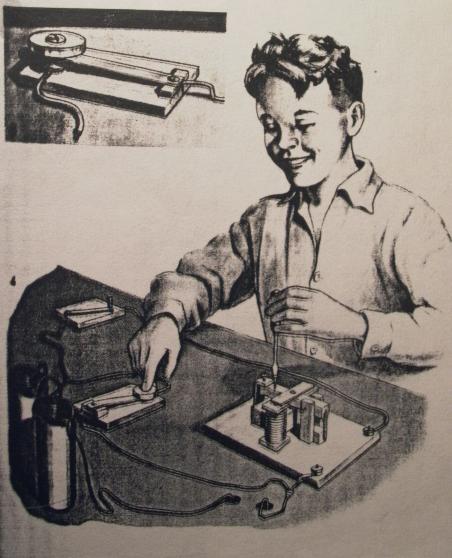
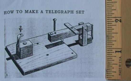
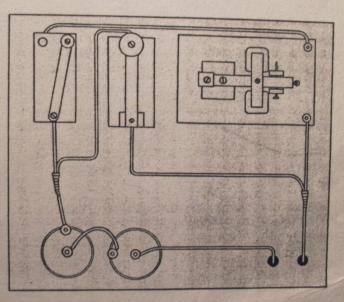
Quoted from original instructions: "The telegraph shown here is a simplified version, made largely of wood, of the standard equipment which is explained in the article on the Telegraph. A good size for this set is about twice that shown in these pictures. This device is a practical application of the magnetic action of an electric current when it passes through a coil" (see illustration above).
1. Sounder
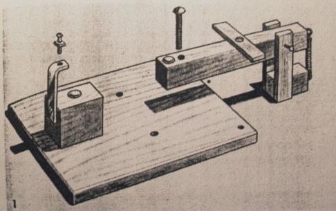
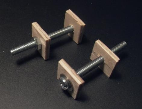
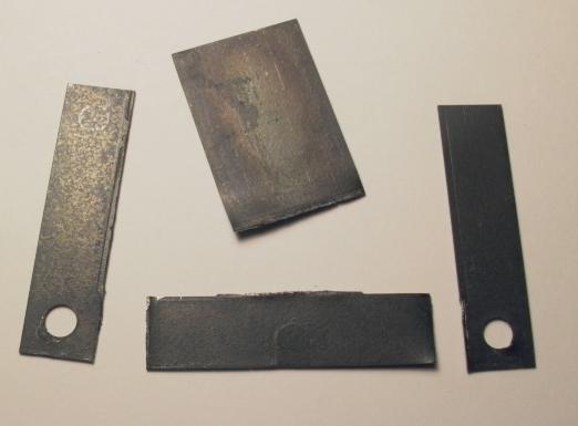
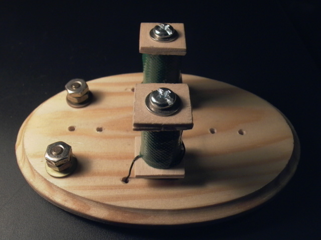
Quoted from original instructions: "Above (left) are all the parts of the sounder except the electromagnets. The sounder lever and bracket are shown assembled with a thin nail for a pivot and small coiled spring at the back. Two machine screws provide stops for adjusting play. One is let through the lever, and the other is placed on the stop strap at the left. Each strikes on the head of a thumbtack. The only metalwork needed is cutting and drilling a short piece of soft strap iron for the armature and cutting, drilling, and bending the stop strap for the stop at the left."
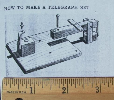
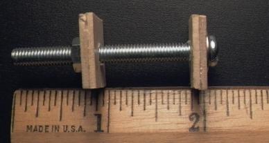
As mentioned above, "...a good size for this set is about twice that shown in these pictures." Therefore, to help you figure out the size, I have included a scale (in inches) below (left and right).
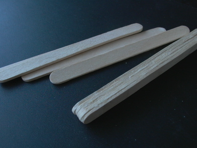
The armature and other wooden parts can be built from scrap wood. Mine were built-up from popsicle sticks (below left). Simply stack to desired thickness, glue together with wood glue or white glue and clamp overnight. Don't forget to protect your work from the clamp with another two popsicle sticks or pieces of scrap wood. When the glue has dried, sand-off the rough surfaces and cut to size. I have photographed a few of the partially completed parts to give you an idea of a "good size" (below right).
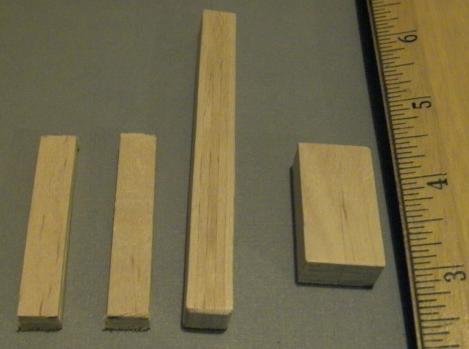
For the base, I used a wooden oval board purchased from the craft section of a dollar store (originally bought for another project). If you wish to use a rectangular board, a good size is about 3" x 5.5" x 0.375" thick (based on my original Bunnell telegraph sounder).
I made the stop strap from a strip of brass (available at hobby stores), cut to size and bent to shape on a vise (drill holes before bending!!!).
2. Electromagnets
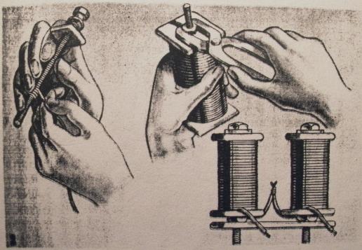
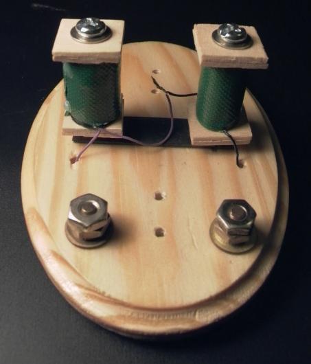
Quoted from original instructions: "Each electromagnet is wound on an iron bolt, with about 100 turns of common bell wire. The coils should be held between cardboard washers. To give them opposite polarity, magnets should be wound in the same direction and connected by joining the wires from inside the coils. Finally, the magnets are mounted on a soft iron strap. The lower bolt ends are set in snug holes in the base. The two free wires are connected to binding posts at one end of the base" (above).
The magnets were wound on 2" machine screws (above). Make sure screws are magnetic (i.e. made of iron, steel, nickel or cobalt) or the telegraph will not work!
Instead of using paper washers, I used wooden washers made from tongue
depressors (available from crafts stores in packages of 100 or more, or
just ask any physician nicely and he/she would be more than happy to help
you). Simply cut a tongue depressor into squares, and glue into stacks
of two, making sure wood grains run perpendicular to each other.
You will need eight (8) squares to make four (4) washers. Popsicles
sticks are not suitable they are too thick and narrow.
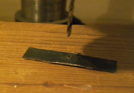
When drilling holes into the wooden washers, begin by drilling a small
guide
hole in the center (you can find the center of a square by drawing an 'x'
by drawing a straight line diagonally from corner-to-corner) and work your
way up by changing drill bits and drilling again into the same hole.
The final hole should be one size smaller than the screws. This will
allow the screws to cut threads into the wood.
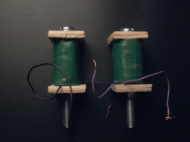
Magnets were wound with about 200 turns of telephone transmission line wire. Both magnets were wound in the same direction. You can also use magnet wire or as mentioned in the original instructions above, common bell wire. Finally, the coil was protected with a layer of electrical tape. In addition, I added a layer of tape made from fabric for extra strength and aesthetics (above right).
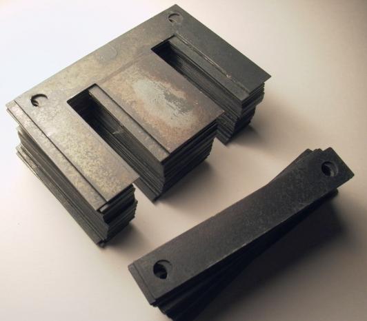
The soft iron strap connecting the two magnets at the bottom is important as it helps to complete the magnetic circuit as it forms a horseshoe magnet. This is where other telegraph plans often go wrong as there is nothing at the bottom to complete the circuit. I used the core of a junked electrical transformer for the iron straps. After taking apart a transformer, core pieces (called "laminations") were unstacked and sorted into E and I shaped pieces of iron (below left). I was able to cut 2" pieces of strap from an E-shaped lamination (below center). A hole on one side has already been drilled, so I only had to drill one more on each piece. The two pieces will be stacked together under the magnets. The remaining 2" piece of iron (without holes) will be used for the strap that will be placed in the middle of the armature (below right).
3. Assembly and Testing
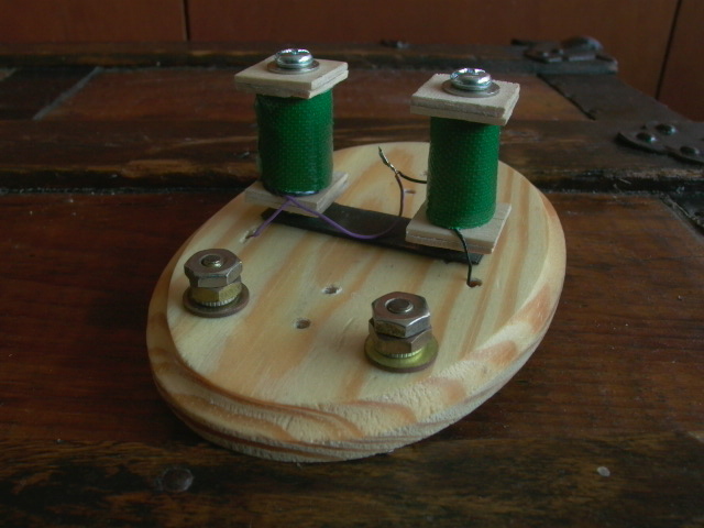
Magnets were then installed and tested (below left). Wires ran under the board and nuts and bolts were used as binding posts. A pair of nuts and washers underneath the board held the magnets in place. Also note the iron straps connecting the magnets. A good place to install the magnets is along the center line across the board. As mentioned earlier, magnets should have opposite polarity. However, the wording in the original instructions is rather confusing. Although, electromagnets were wound in the same direction, current must run in opposite direction (i.e. clockwise through one magnet, counterclockwise in the other) for opposite polarity. Therefore, the exit end of one coil should be connected to the exit side of the other magnet.
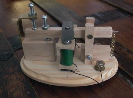
The rest of the telegraph set was assembled for testing (above right). I used brass for the stop strap (available at hobby stores) or you can use a piece of lamination from the transformer core. Small wood screws were used instead of thumbtacks, and the spring came from a ball-point pen.
To test the telegraph, apply 4.5 to 6 volts of DC to the binding posts (do not apply current for more than two seconds in duration or the magnets will become hot). The armature should move down. If there is no movement, check see if the electromagnets are working (the tip of the electromagnets should stick to a magnetic object such as a screwdriver or Canadian 10-cent coin). If there is magnetism but no movement, either the pivot or spring are too tight or the iron strap needs to be lowered (I had the latter problem). If the iron strap needs to be lowered, it can be done by adjusting both the screw on the stop stap and the machine screw on the armature (the one that hits the thumbtack on the wooden block). This might work, but in my case, it didn't help at all so I had to carve out a recess across the middle of the armature to "sink" the iron strap further down a little more. This finally worked for me. As a last resort, you could also lower the pivot by cutting down the two vertical parts of the bracket. Of course, you may have to shorten the spring.
4. Final Assembly and Testing
Once I got it working, the telegraph sounder was disassembled in preparation for finishing of the wood. It could also be painted but mine was simply coated with varnish. After the final coat of varnish was dried, desired smoothness was achieved and the set was re-assembled. Magnets were re-installed first, and were connected together with silver alloy solder for improved conductivity.
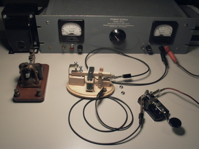
After assembly, the telegraph sounder was tested again (below). At 10 volts, the electromagets drew about 4 amps of current. Therefore, magnets were wound to 2.5 ohms in total. Note the original telegraph key, used for the test.
5. Wiring and Adjusting
Above right: Quoted from original instructions: "The instruments should be connected to two dry cells. Attach the wires as shown. The most important adjustment is that of play in the sounder lever to make it respond instantly to incoming current. This is done as shown [in the illustration at the top of the page] by moving the two adjusting screws (stops) until the lever gives satisfactory clicks. [Above right] is a diagram of the complete installation."
6. Sending Key
Quoted from original instructions: "Fasten one end of a strip of thin spring steel to a base and attach a wooden button to the other end. Place a nail or screw in the base beneath the button to serve as contact when the button is pressed down. A simple throw switch, to close a circuit for receiving, completes the circuit"
Refer to illustration at the top of the page. I will not be building the key as described in this set of instructions. There is no other mention of the throw switch.
Click here for a high quality homebuilt telegraph key.
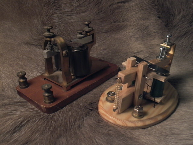
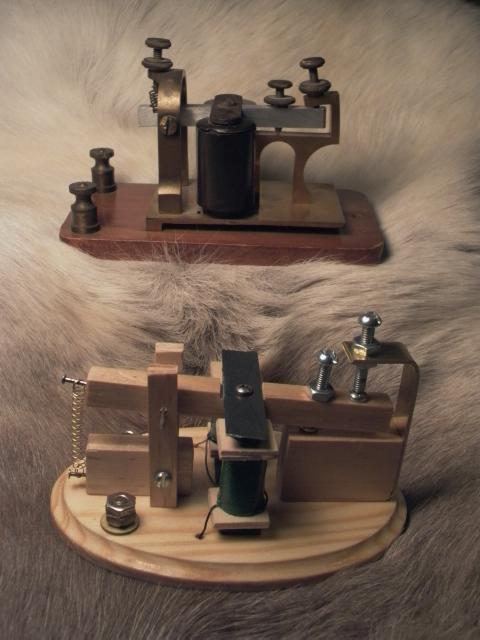
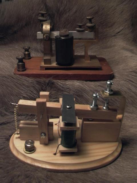
Above: Simplified homemade telegraph sounder pictured with an antique 4-ohm Bunnell "local" telegraph sounder on the reindeer skin rug. "Local" sounders, powered by wet cell batteries, were usually wound to 4 ohms (resistance) and can not be connected to a telegraph line without a relay. "Mainline" telegraphs, on the other hand, were designed to connect directly to telegraph lines and were typically wound to 100 to 200 ohms (resistance) or so. If you're not sure which one you have, you can always check with an ohmmeter (Caution: clean the binding post contacts or you will get a false reading of high resistance!). Local sounders work well with 1.5 volt dry cell batteries. I do not allow food and drink on the reindeer pelt rug, let alone wet cell batteries!
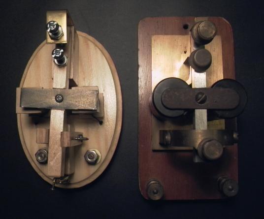
Below: Top view of the telegraph sounders.
Other Links of Interest
My Telegraph
Key Project: A companion for the project on this page. Can be
used for ham radio (CW) as well.
Telegraph Sounder
by The Steampunk Workshop: A realistic working replica of a telegraph
sounder. Involves metal fabrication and machining.
The Telegraph Office:
Pictures of telegraph instruments. Do not visit this site unless
you have a lot of spare time. :)
W1TP's Morse and Telegraph Site
How to Build Simple Telegraph
Sets: Another site presented by W1TP, with simpler telegraphs.
Tools of
Telegraphy
More Links
Created On: March 28, 2008
Updated: March 29, 2008