Here is a simple little three-transistor FM wireless microphone / room bug that can really throw-out quite a signal. With a wide tuning range from 80 MHz to 120 MHz, this little device can transmit anywhere within the FM broadcast band (88 to 108 MHz) and can be heard with any standard FM broadcast receiver. A simple modification (described below) allows the mike to operate above or below the FM broadcast band. Transmission is line-of-sight, so radius of coverage and be anywhere from 300 feet (indoors, with 9" wire antenna) up to 1 km or more using a properly matched 1/4 wave monopole ground plane antenna on a rooftop in the open countryside. For best results, I built this project on a 2.5" x 3.5" printed circuit board. Schematic diagram, printed circuit pattern and component layout diagram are shown below.
Warning: This device is for educational purposes only!!! It is NOT to be used as a bug. Please keep experiments legal. It is your responsibility to check with local law authorities to determine the legal implications if you use this device. Information on this page is provided as a courtesy for educators, students, and hobbyists.
Feel free to printout digrams and parts list for you own use. This page isn't going anywhere, so you may bookmark this page for later use if you have a del.icio.us account.
Note: This microphone was built as part of a school project when I was a kid, which was FCC Part 15 compliant at the time. This may or may not be the case today. I no longer have the project with me as it had been damaged (connected to an HV power supply in error, accidentally "frying" the parts with 200 volts DC!).
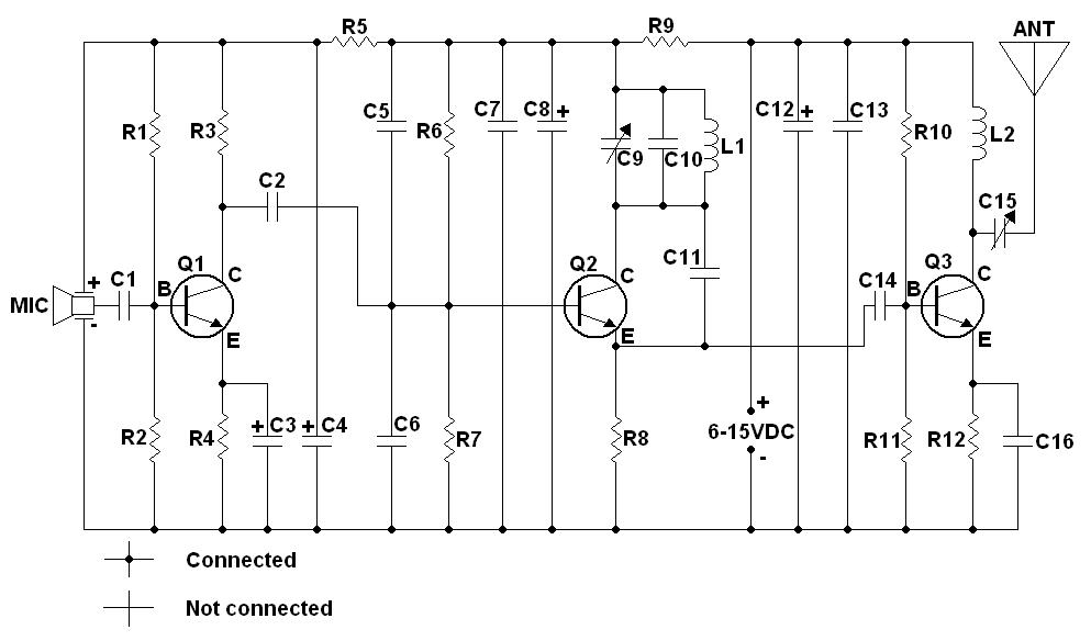
Schematic Diagram
Parts List
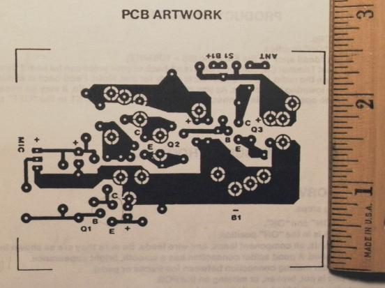
Printed Circuit Board Pattern
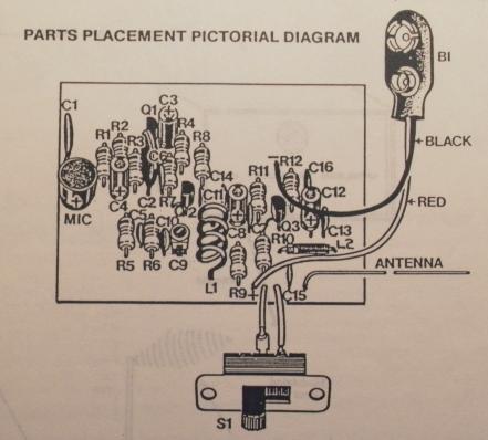
Layout of Parts
Construction Notes and Tips
For best results, the FM wireless microphone should be built on a printed circuit board using the pattern shown above. Keep connections as short as possible (especially in the RF sections!), as excess lengths can introduce stray inductances and/or signal loss.
The 2N3904 transistors can be substituted with almost any small signal NPN transistor with an Ft rating of about 200 MHz or greater, such as a 2N2222, 2N2222A, PN2222, PN2222A, BC108, BC108A, etc.
Coil L1 is by wrapping 4 turns of #18 coated enamel wire (cut to 4") around a 1/4" smooth rod or shank of a drill bit. Remove the drill bit and stretch coil to 5/8" length. Remove 1/4" of insulation from both ends and solder to PCB and cut off extra length.
Note the polarity of the condenser mike (fat prong is positive) and location of flat side of trimmer cap (see pictorial diagram). All transistors and electrolytic capacitors (marked with polarity on schematic) MUST be installed correctly or mike will not work.
In the original kit, C15 is a 100 pF fixed capacitor, not a variable cap.
The antenna (marked "ANT") in the original kit consists of a 9" length #18 enamel wire. Remove 1/4" of enamel insulation from one end and connect and solder this wire to the PCB hole marked "ANT". Cut off any excess lead length.
Modifications (For Informational Purposes Only)
With a simple modification, the wireless microphone can be made to transmit on the VHF "scanner frequencies" above or below the FM broadcast band. Of course, this means you will not be able to tune-in on your mike with an ordinary AM/FM radio. To operate above 108 MHz, simply remove C10 and use a 3-turn coil for L1 instead of the 4-turn coil. This mod will enable the mike to transmit in and around the VHF "high band" region (i.e. 137 - 174 MHz) where many two-way radio services operate. However, unlike VHF communications services, in which narrow-band FM is used, your microphone transmits wideband FM like the standard FM broadcasts, therefore you will need to use a VHF receiver with an analogue slide-rule dial that can cover a region between above 108 MHz, such as a multiband radio with a weather band or a World War 2 vintage Hallicrafters model S-36A communications receiver if you are lucky enough to find one. If you use "police band" scanner, you will hear a lot breaking-up in the audio (if you have the noise squelched off) due to wide frequency swings.
To operate on a lower frequency below 88 MHz (i.e. VHF "low band"; 30 - 54 MHz), simply add one more turn to L1 and/or replace C10 with a 15 or 20 pF capacitor. 54 - 88 MHz is used for TV channels 2 to 6; if you have an older television set with a sliders for each channel, try using your TV as a receiver.
I do not recommend transmitting any higher than 160 MHz as tuning becomes very unstable. If you wish to operate your bug in the 420 - 470 MHz UHF band, a better idea is to use frequency multiplication (doubling or tripling). This can be done by operating Q2 (oscillator) at a lower frequency (the fundamental frequency) and by tuning the ouput of Q3 (amp) to a 2nd or 3rd harmonic of the output frequency of Q2. For instance, if you wish to transmit on 435.5 MHz, oscillator Q2 is tuned to 145.17 MHz while output of amplifier Q3 is tuned to its third harmonic at 435.5 MHz. In this case, Q3 acts as frequency tripler. Frequecy multiplication involves redesigning the stage after Q2, which I shall leave to the experimenter.
If you have an RF wattmeter, here's an experiment you can try: use a trimmer cap for C15 instead of a fixed 100 uF cap. Run the output of the mike into a dummy load (i.e. a resistor) that's equal to the impedance of the anntenna you wish to use via the wattmeter, and adjust C15 for maximum output. Now you'll have a better match between the transmitter and the antenna and therefore, reduced loss. You will need to readjust C15 when you change the frequency. Once again, be sure to check with local law authorities before proceding with further experiments.
Good luck!
Created on: Feb. 29, 2008
Updated: March 29, 2008
January 9, 2010 (added legal information)