Build an Old English style crystal set radio receiver with an Australian circuit and experience an unexplained mystery phenomenon in action, listen to music, tune-in on the world, and more!
Introduction
The crystal radio, or “crystal set”, is a radio receiving circuit that does not require an external power source to operate. Running only on energy from radio waves, crystal sets were used by many pioneers in the early days of broadcasting and wireless communications. The first commercially available crystal sets in the early 20th century were expensive and thus, DIY radio kits and building from scratch were popular alternatives. By the 1920’s, crystal radios fell out of favor as home entertainment devices but its popularity as a boys’ hobby continued into the 1970’s as kit manufacturers such as Heathkit and Eico offered crystal receivers.
Because crystal sets have neither power supplies nor amplification, they offer clean and true high-fidelity audio. The lack of power supplies means no power line noise. The lack of amplification mean no tubes and therefore, no annoying filament/heater hum, and also no transistors means free of harshness in the audio. As such, crystal radios are used by some audiophiles today.
While crystal radios are simple and fun to build, the majority of crystal sets built today are ugly in appearance, with a bunch of wires, pins, and other components all exposed on a piece of wood. In this challenge, I have decided to take it a step further to try to build a crystal radio that (1) does not look like a kid’s science fair projects and (2) looks beautiful on a display shelf. I based my design on old English crystal sets such as the Gecophone in which the set is housed in a wooden enclosure box. For the working circuit, I used the 1932 Australian “Mystery” design. Well known for its sensitivity and simplicity, and despite being popular, nobody knows exactly how the “Mystery Set” works to this day (more on this later).
Theory of Operation
Crystal set circuit design can vary from simple to intricate, but the basics of operation is the same. Figure 1a shows a simple crystal radio circuit. Signals in the air are captured by the antenna, inducing weak currents that alternate at the frequency of the signals. The coil L and variable capacitor C1 (or “condenser”) in parallel forms a resonant circuit (or “tuned circuit”). The frequency of resonance can be adjusted (“tuning the radio”) via the variable capacitor (in older designs, tuning is achieved by adjusting the position of a set of coils or changing the contact point on a coil in what is called a variometer). A parallel LC tuned circuit gives high impedance for the signal of the frequency to which it is tuned, thus shorting all frequencies above and below resonance to ground, acting as a filter to capture the frequency of interest. A mathematical equation can be used to determine resonant frequency of a parallel tuned circuit, or click here for an online resonant frequency calculator.
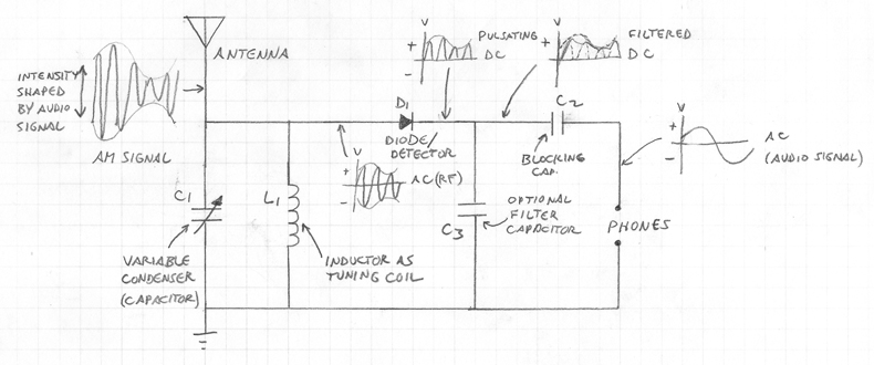
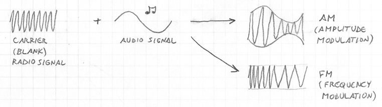
Filtered from the tuned circuit, the AC signal goes to the detector. If the signal carries information in the form of AM (amplitude modulation), the AC signal has a varying intensity (voltage) in which its rate of variation is equal to the frequency of the audio signal being carried. The detector is a one-way conduction device which allows only the positive or negative phase (not both) of the AC to pass through resulting in a pulsating DC signal and in this case, DC of varying intensity. The variable voltage DC signal is then fed through a blocking capacitor, which removes the DC component while allowing the varying intensity to form a new AC signal. This new AC signal alternates at the rate of the variation in intensity of the previous DC, which is now essentially the audio signal that is fed into a high impedance headset (the earpiece or headphone is called a “telephone” in early 20th century British wireless terminology, or “phone” in America).
Early crystal radios had detectors that consisted of a needle (called a “cat whisker”) on a crystal of metal ore such as pyrite or galena, or metal oxide such as rust or oxidized copper (as you might have already guessed, the mineral is the origin of the word “crystal” in “crystal set”, and the “cat whisker” evolved into symbol of the detector). However, finding the optimal point on a crystal requires patience and can take awhile; thus, many crystal set builders have turned to diodes which can be had for less than a dollar. Because voltage in a crystal radio circuit is small (fractions of a volt), only diodes with a low activation voltage can be used. Germanium diodes with a threshold voltage of around 0.3 volts are most often used in crystal sets. Introduced in the 1940’s, the 1N34 is the most popular choice (the 1N34A is the modern equivalent). Alternatively, one can use the PN junction of any germanium transistor as a detector. Silicon Schottky diodes, which are essentially cat whisker diodes with silicon crystals, have a threshold voltage of 0.2 to 0.3 volts and can also be used. On the other hand, conventional silicon diodes containing P-type and N-type Si crystals have a turn-on voltage of 0.6 volts and usually will not work unless the signal is very strong or an external power source is used to “turn-on” the diode (bias voltage).
I will not be getting into any math and physics behind radio engineering as there are many books and websites on the topic.
Circuit Design
For the circuit, I modified the design of the Australian “Mystery Set”. First introduced to the public in the summer of 1932, the Mystery Set is a very interesting design that, to this day, no one knows for sure why it works. When it was originally built, there was an error in wiring (see fig. 2a below) resulting in an incomplete circuit in the tuning section (the “front end”). According to the basics of circuitry, the design should not work at all…however, not only did it work but the error actually gave improved performance!!!
The main unique feature of the Mystery Set is that the tuning coil performs a dual function as an impedance matching transformer. Carefully designed coils and transformers are the secret to “high performance” crystal sets. In my modification (fig. 2b), I added an extra coil to increase inductance to enable longwave (LW) reception, and a parallel coil to reduce inductance for shortwave (SW) reception. A switch connects the extra coil and/or shorts out portions of the coil, and acts as a band switch to select LW, MW (local AM broadcast), and SW.
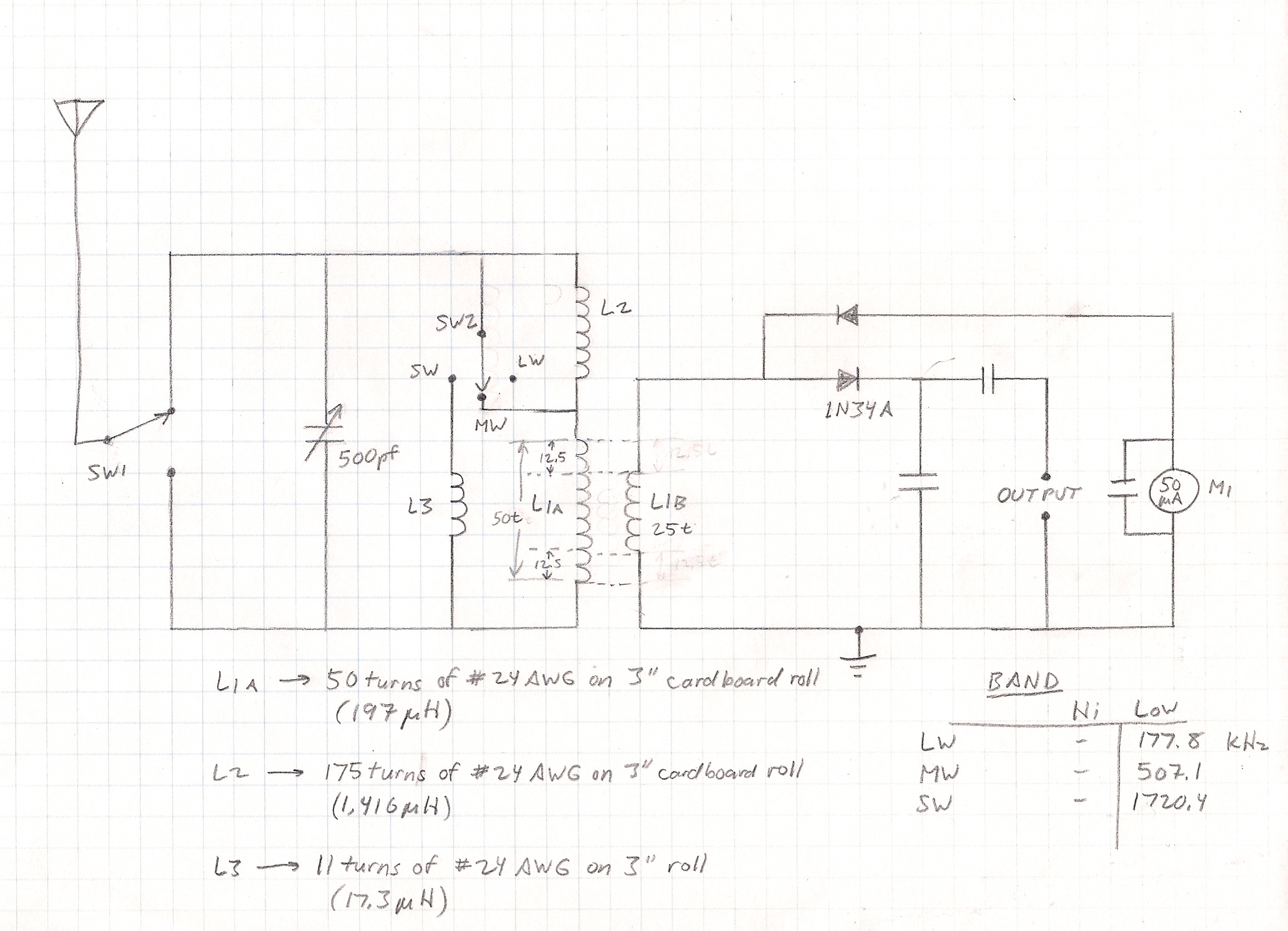
I have added an extra detector in order to make use of both positive and negative phases of the incoming signal. One phase feeds the headphones (or “line-in” audio input jack of an amplifier) while the other feeds a 20 µA ammeter that can be used to indicate signal strength or assist in tuning.
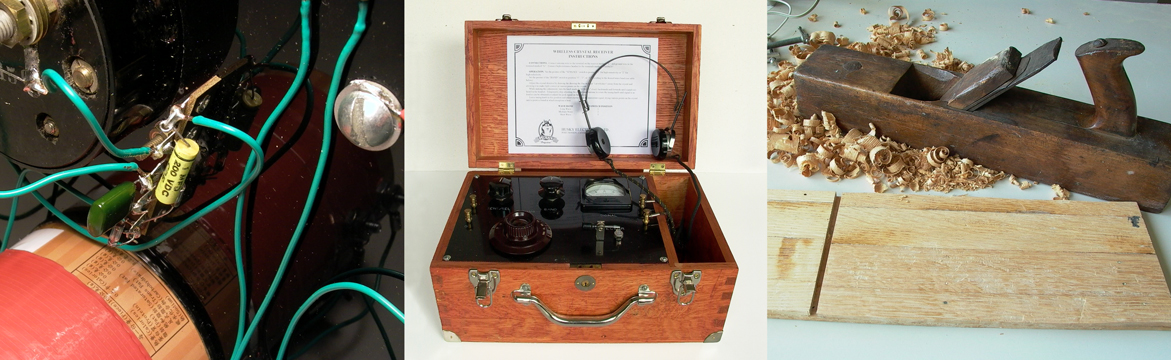
Collecting Parts
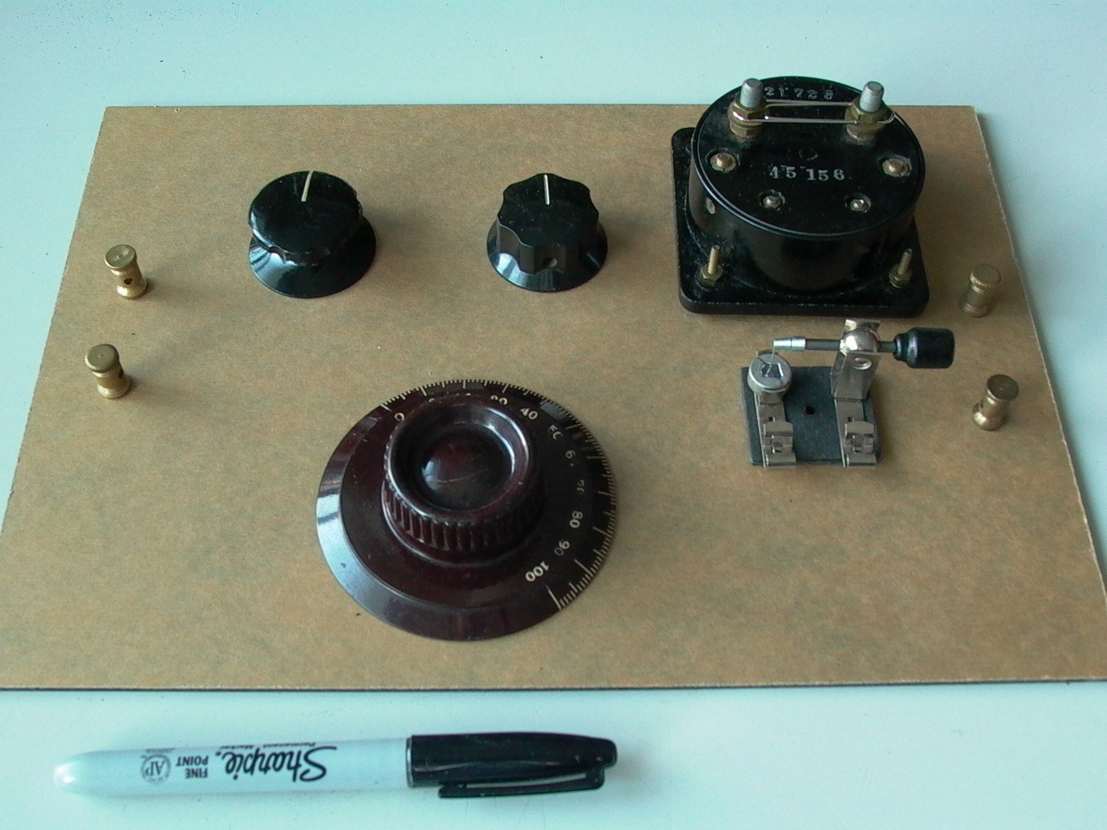
I have been wanting to build this project for years and as such, I have been collecting parts (fig. 3), some of which are antique and/or NOS (new-old-stock). Due to changes in plan, not all components were used.
Winding the Coil
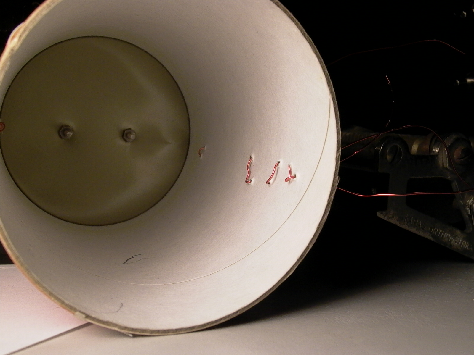
Once I was ready, the first step was to wind the coil. I used an old 3″ diameter paper tea can for the coil core and 24 AWG magnet wire for the coils (fig. 4). End points were marked and punctured (fig. 5) for binding posts (later), and coil wound (fig. 6) according to circuit diagram (fig. 2). The secondary coil of L1 was wound side-by-side with the primary; this is called “bifilar winding”. The shortwave coil was wound on the same can. Tape was used to hold the coils in place (fig. 7). NEVER use masking tape for anything permanent as the adhesive would dry up over time…I learned this the hard way many years ago.

I will work on the longwave coil for later when I have some more time.
The Font Panel
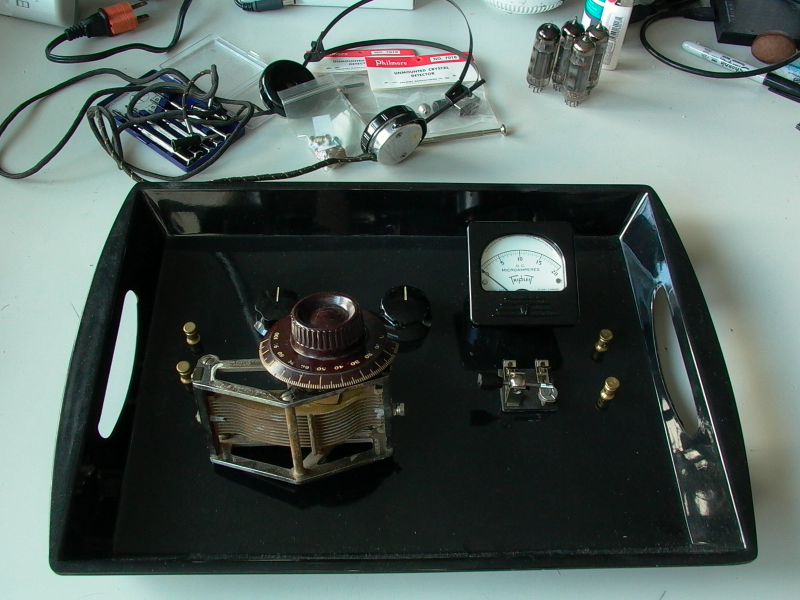
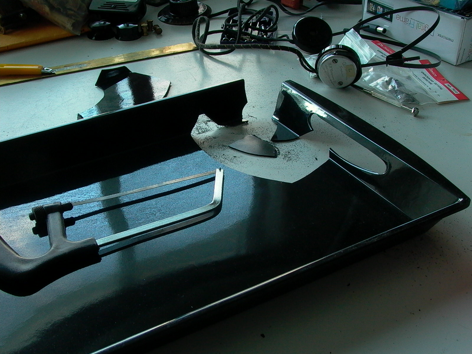
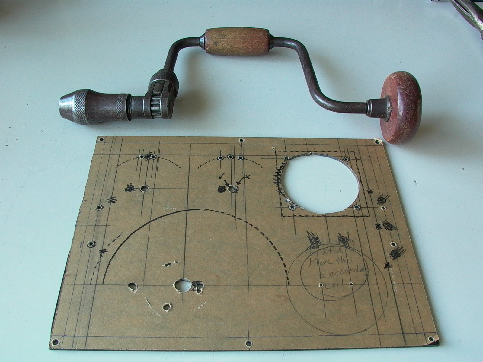
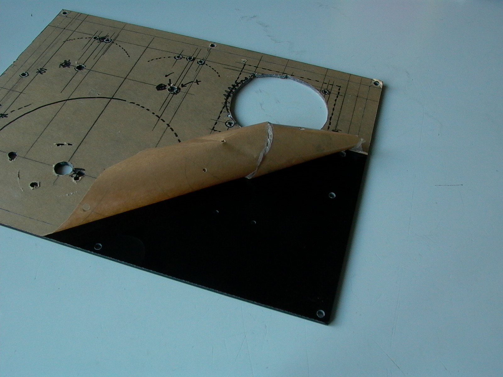
The next step was to design the layout of the front panel. A placement test was done on a black melamine tray (fig. 8); however, as shown in figure 9, I learned the hard way that melamine is extremely brittle and very difficult to cut.
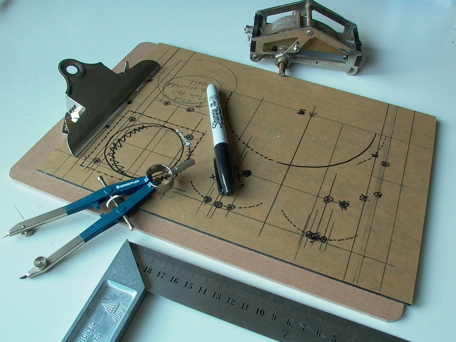
Failing the first attempt, I went with a sheet of black translucent acrylic instead. Another placement test was done (fig. 10) (there is a brown protective sheet on the piece of plastic), and when I was satisfied, positions were marked and drilled (figures 11 to 13).
Notice the old style telegraph binding posts? Those were made by Mr. John Infurna, a collector of antique telephones who is well known among his circle for his highly accurate custom reproductions of rare antique telephones and phone components. Experts have not been able to distinguish Mr. Infurna’s replica objects from originals but don’t try to pass off his repros as originals…Mr. Infurna himself can tell right away and have caught – and reported – a few sellers doing so on that auction site everyone uses.
Making the Rotary Switches
Rotary switches on many early crystal sets had external contact points. Electronic components stores do not sell these, so the only option was to make my own switches. These would have to be built directly on and into the front panel.
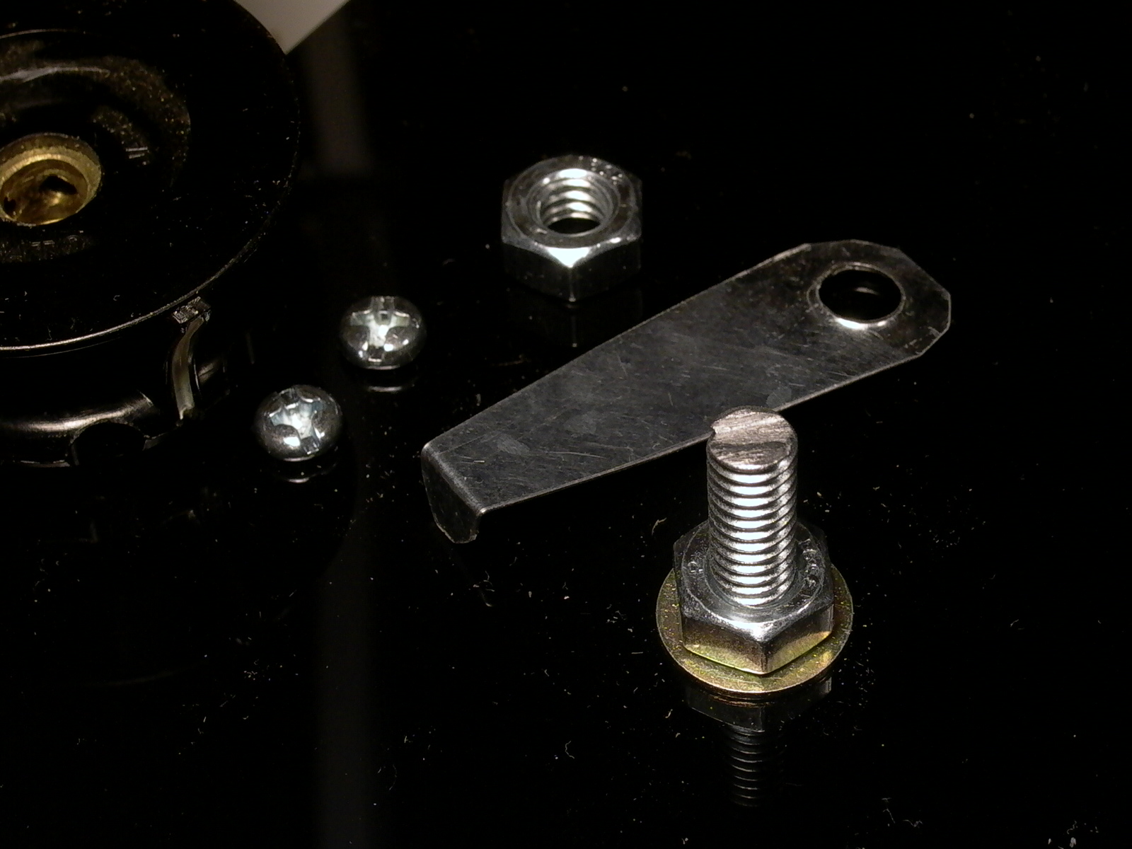
For the contact strip, I used plant labels (made of steel) from the dollar store (fig. 14), cut to shape and sanded. A hole was drilled (fig. 15) to allow a 1/4″ diameter machine screw to go through (the screw will be the shaft of the knob). Figure 16 shows the contact strips after shaping and sanding, and knobs that will be used with the dials.
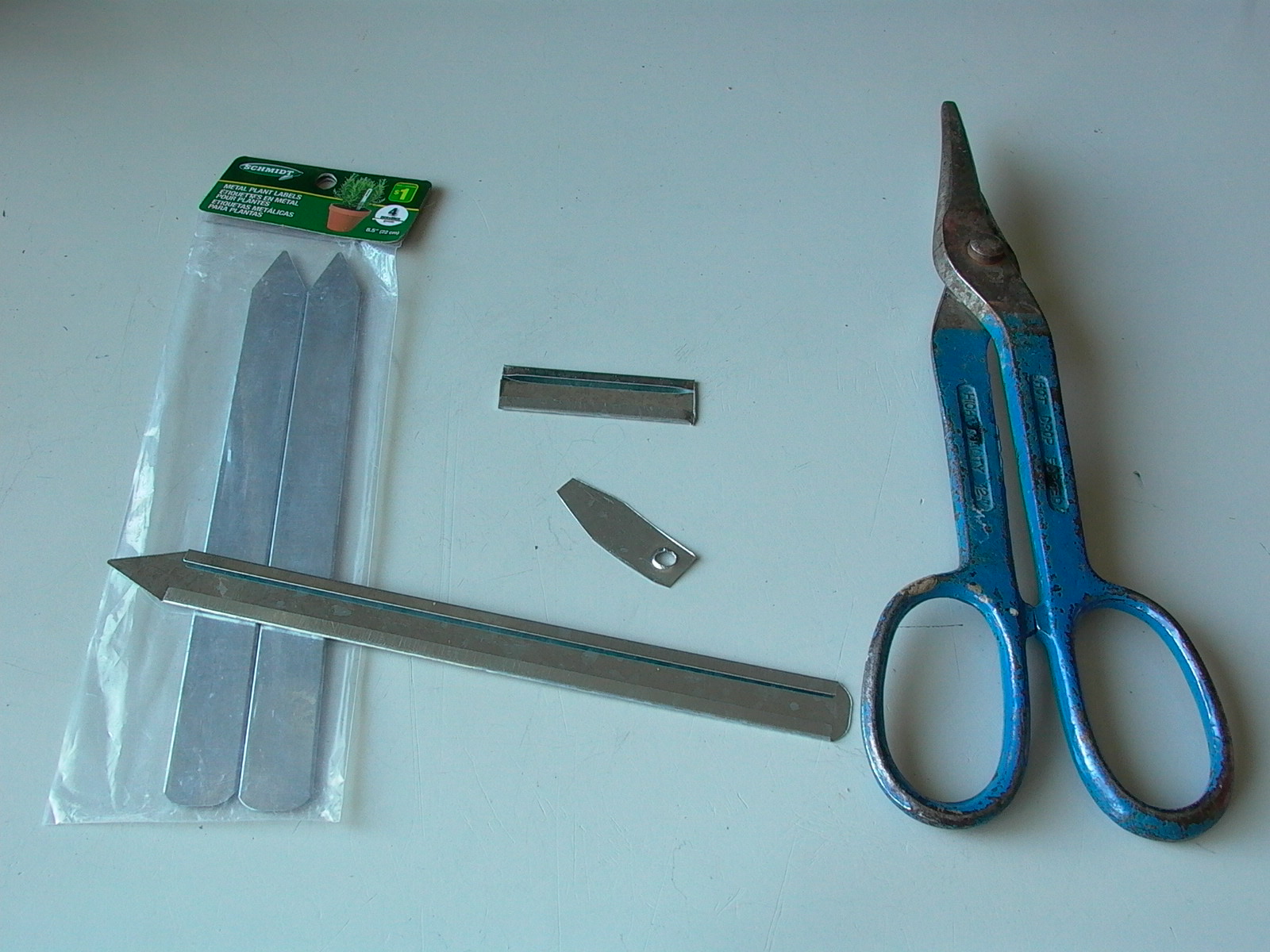
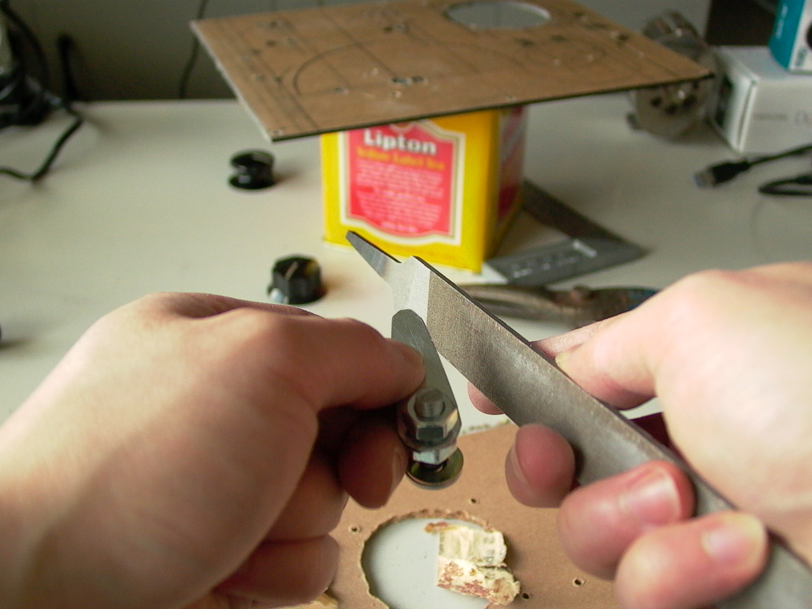
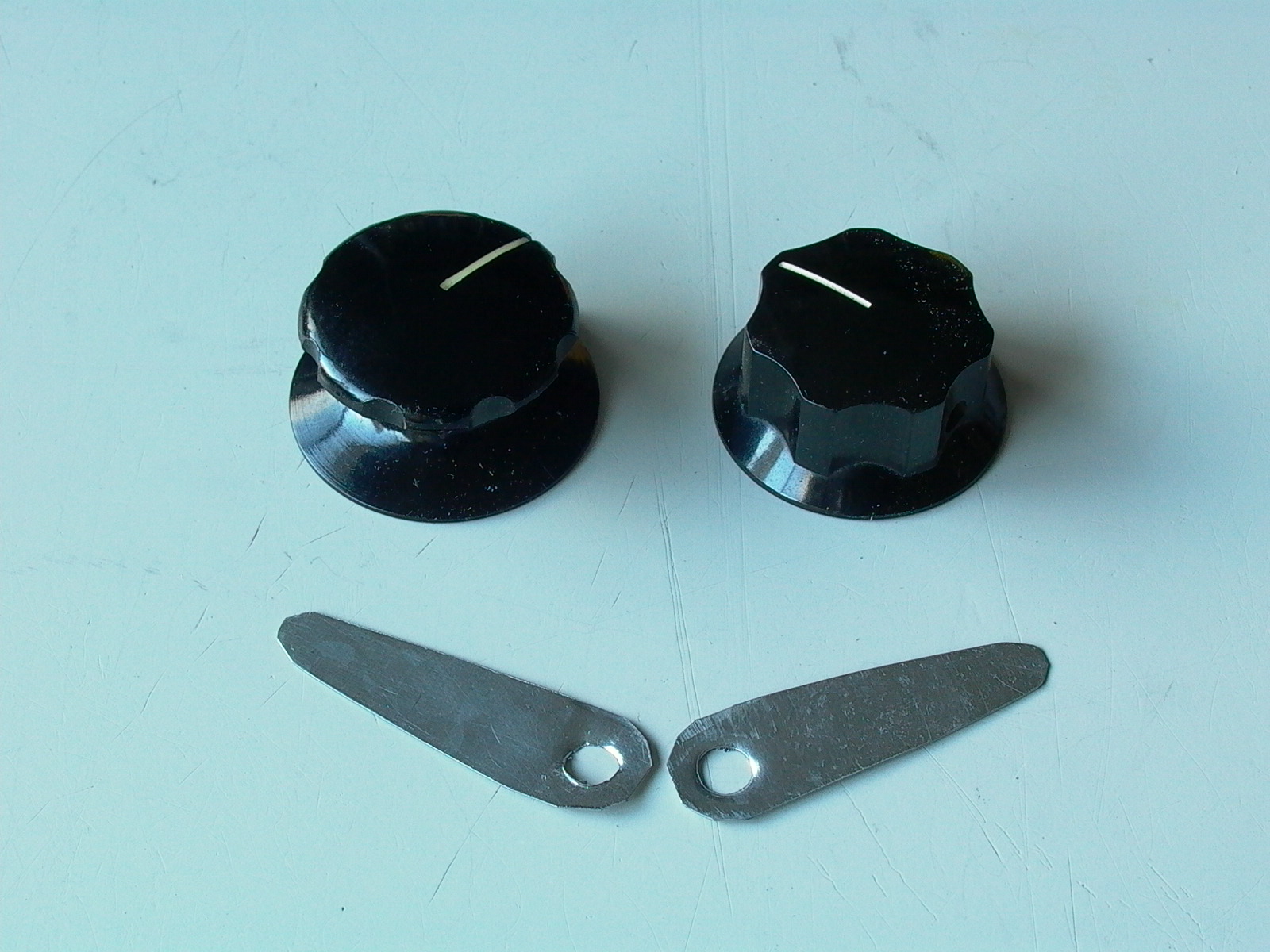
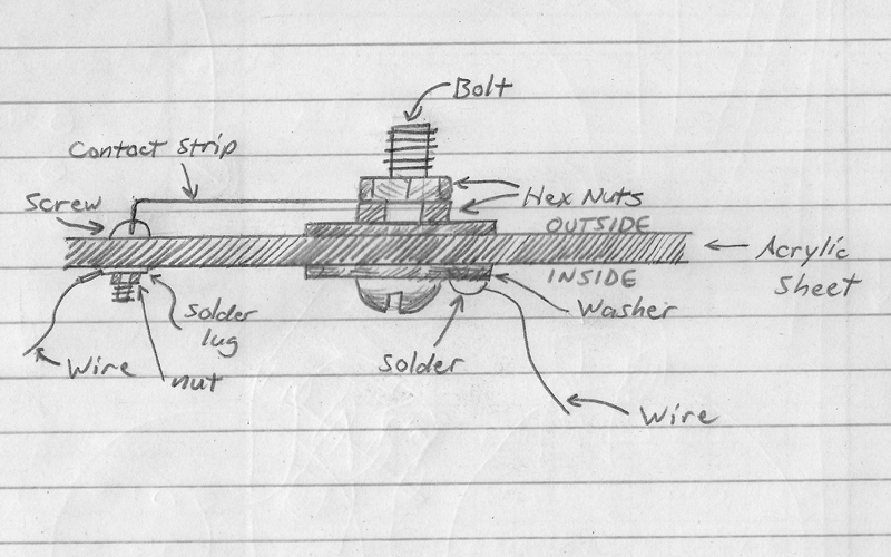
Figure 17 illustrates the order in which nuts and bolts are installed. The nuts should be just tight enough so that the bolt can be turned with two fingers with some light force (i.e. not too tight and not too loose).
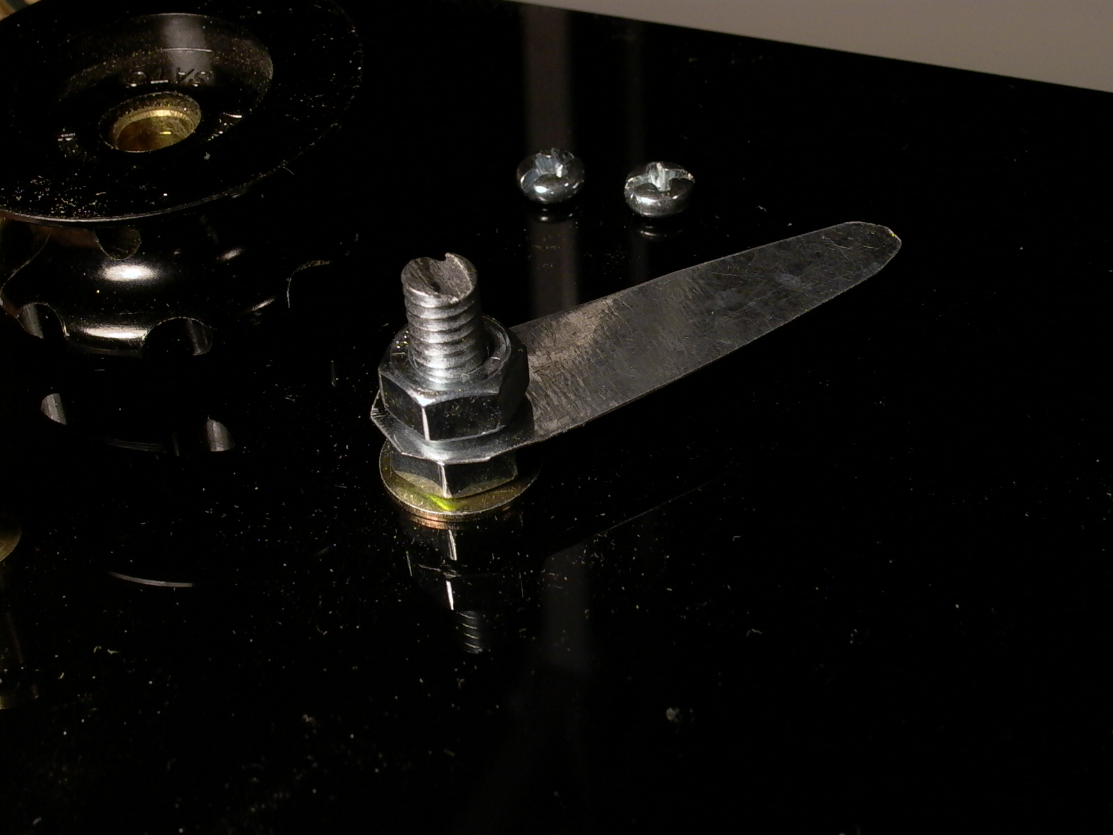
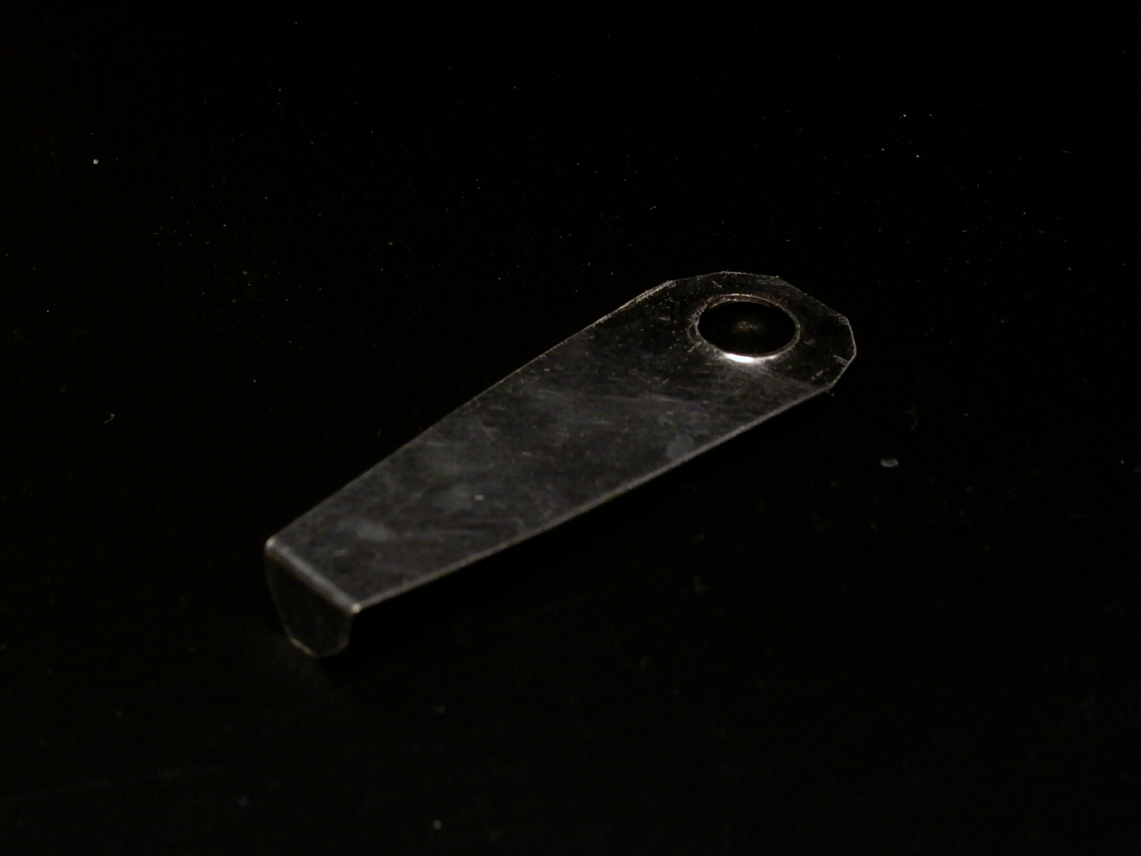
Round headed machine screws were used for the contact points (fig. 18) and contact strip installed. As there was a gap between the contact points and the pointer, the metal strip was remove and bent at its tip (fig. 19) and re-installed (fig. 20). The bolt was then cut to length to accommodate the setscrew knobs. At the end of the project, or when components are installed in place and wired up, the screws can be filled with solder. However, I opted to leave the contact screws as-is in case I wish the make some modifications in the future.
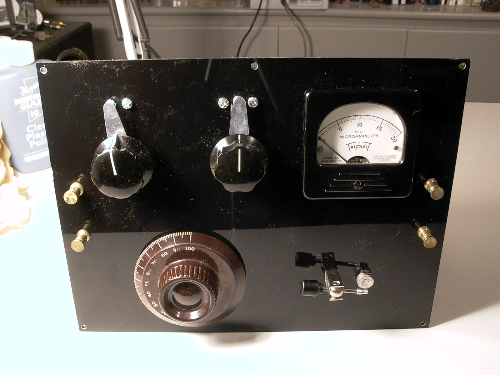
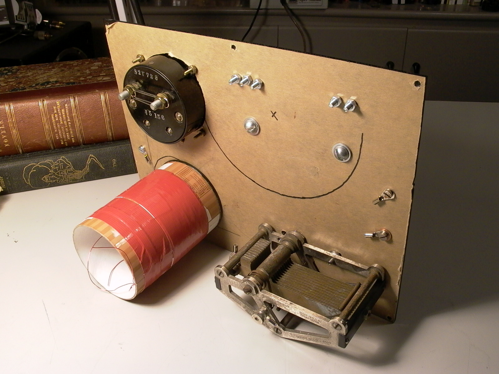
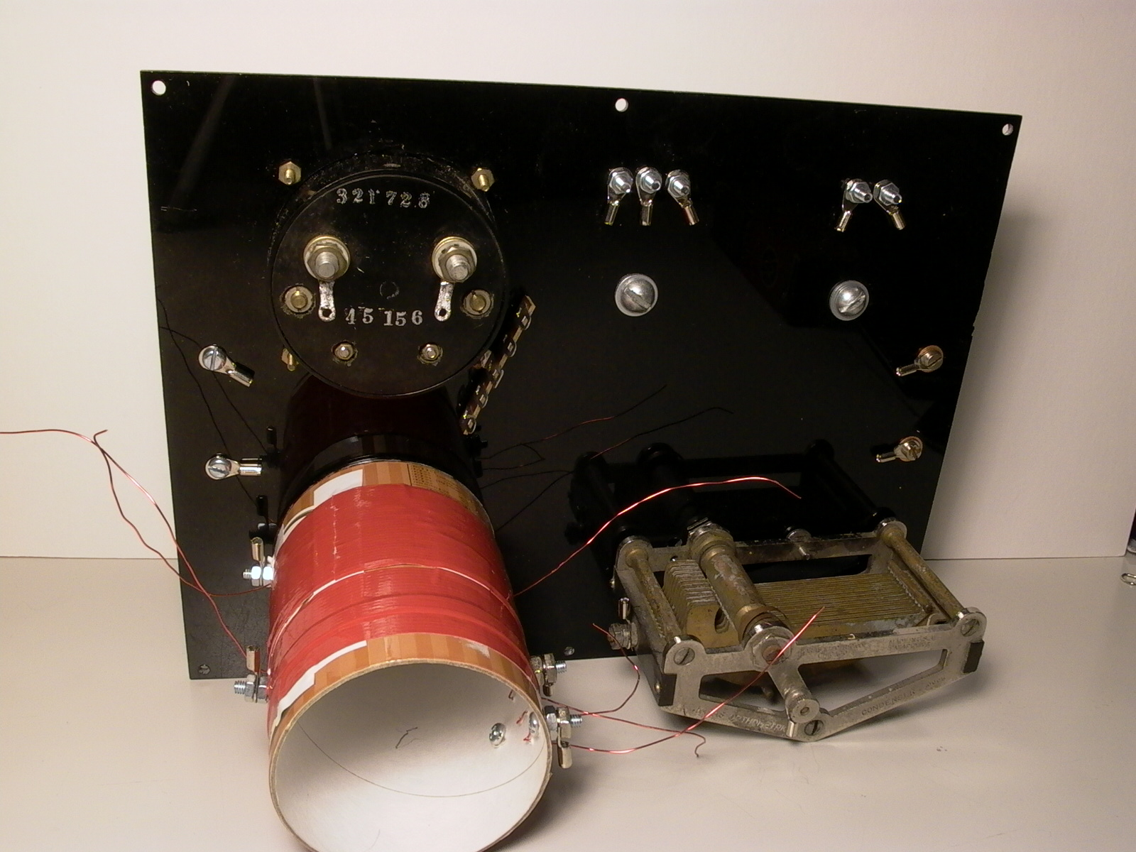
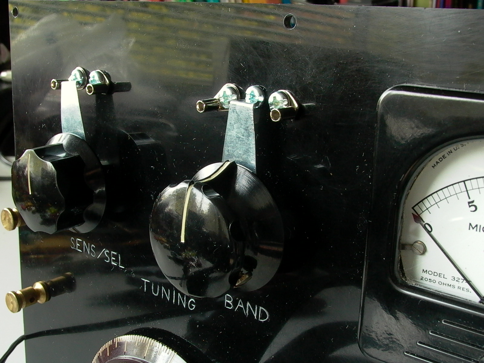
The rest of the panel components were then installed but not yet wired. The front can be seen in figure 21; figure 22 shows the back with its protective sheet still on.
The external Philmore crystal detector on the front panel is a dummy as germanium diodes will be doing the work. The other end of the crystal detector’s screws were used to hold the coil in place (fig. 23). As soon as I was satisfied with they way things looked, components were removed in preparation for the next step
Engraving and “Unpolishing”
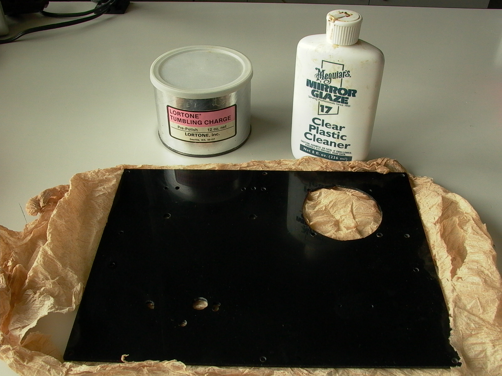
One problem with the black plastic panel was that the surface was too shiny and looks very much like a sheet of acrylic. In order to emulate to look of Ebonite (hard rubber) or Bakelite (phenolic plastic), both of which were commonly used in early electrical items, the surface was roughened up with pre-polish rock tumbler powder (fig. 24). A liquid plastic polish (Meguiar’s Mirror Glaze formula 17) was then used to smooth the surface, resulting in a semigloss finish. If rock tumbler grit is not available, you can use fine steel wool to scratch up the surface by rubbing in circular motion as you move along the surface.
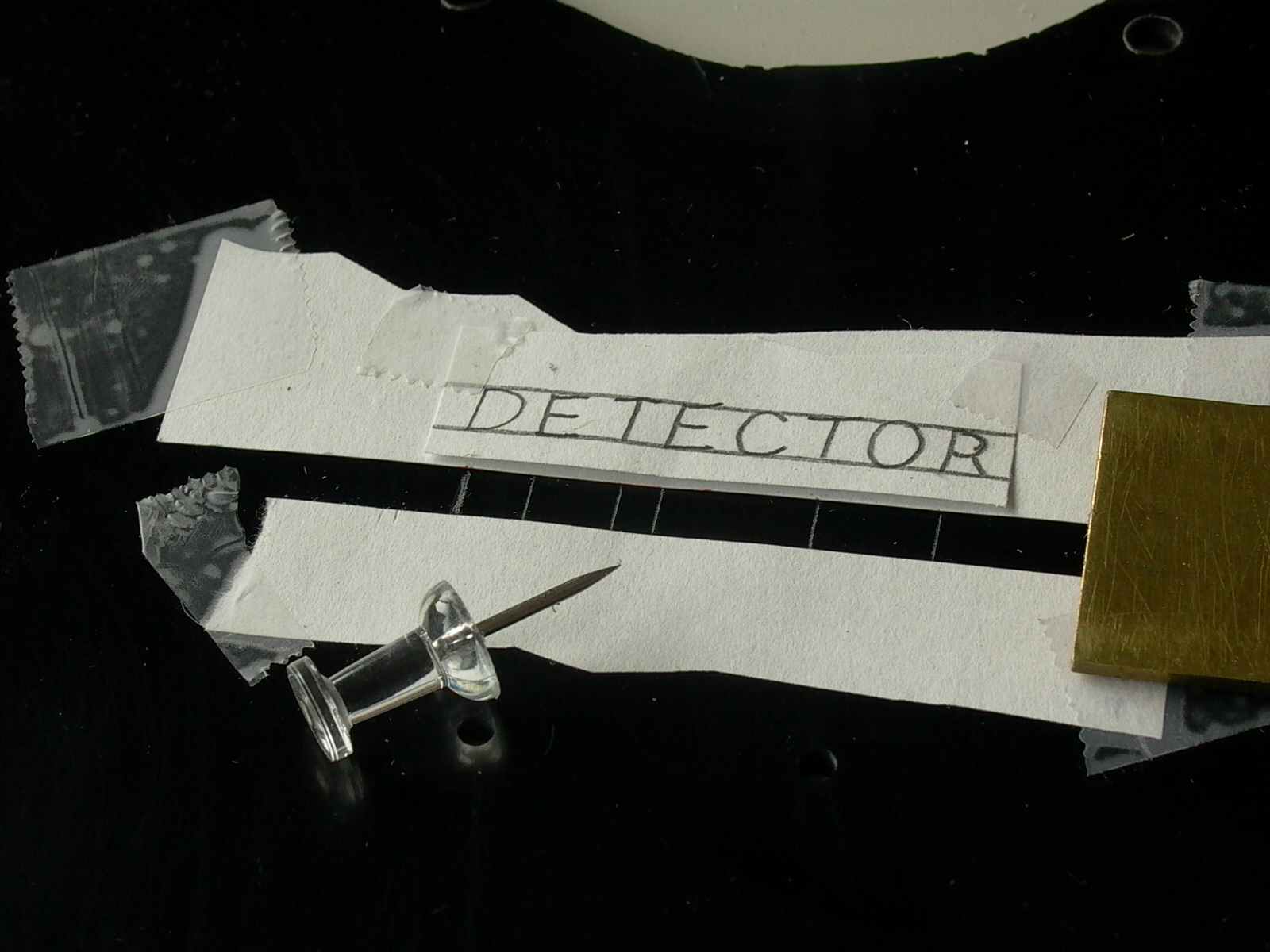
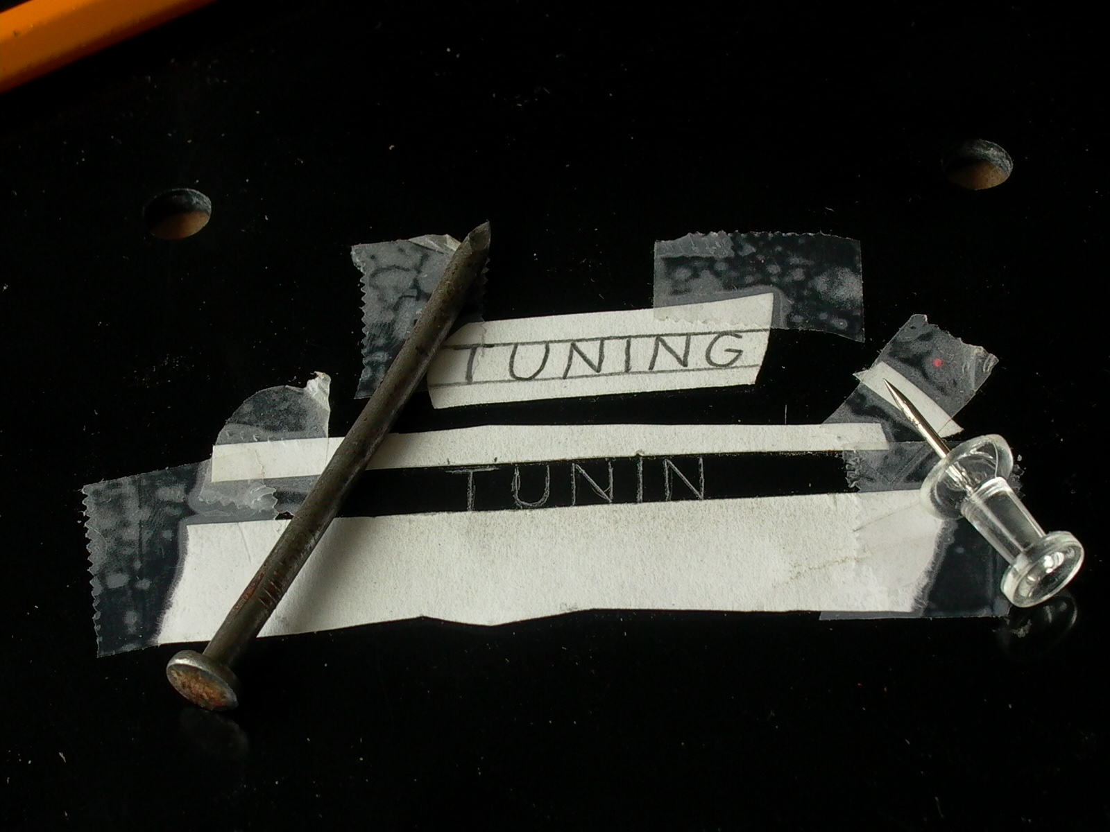
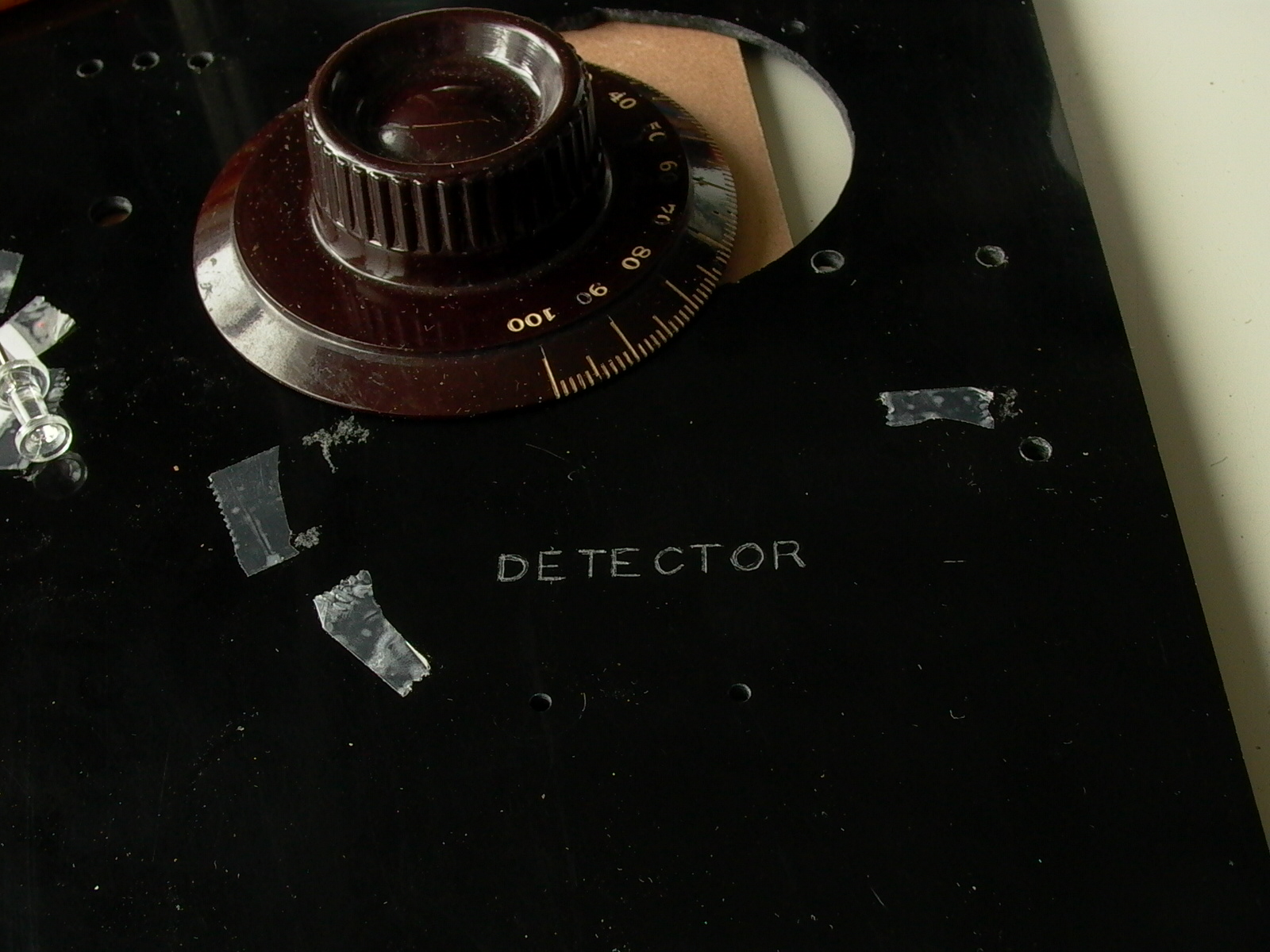
The front panel was then engraved with labels for the dials. Strips of paper taped down were used as guide lines, and lettering was first scratched-on with light pressure using a pin, going over each line multiple times. When letters were sufficiently deep enough, a nail was used to engrave. Finally, the letters were filled with white acrylic paint by pouring a drop over the letters, spreading with a Q-tip and wiping off the excess on the surface with a Kleenex (below/figures 25 to 29).
Re-Assembly and Circuit Wiring
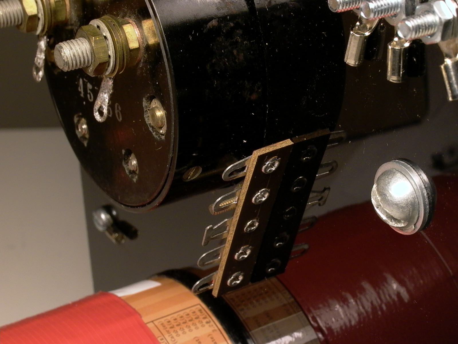
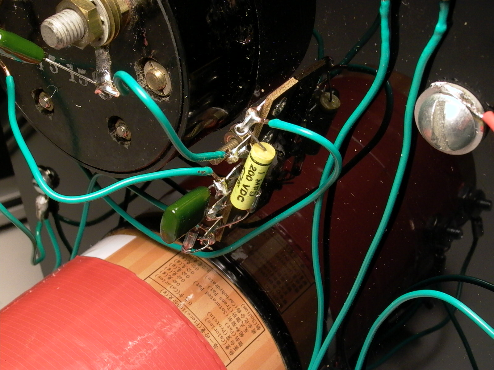
It was now time to re-install the working components and wire them up according to the diagram (fig 2b). Binding posts were add to the coil (fig. 30 and 31) for easy wiring and later modifications, and then installed with the rest of the components (fig. 32). A terminal strip was added (fig. 33) to accommodate the other circuit components such as the diode detectors and other capacitors (fig. 34). Although these capacitors are rated to high voltages for use in tube-type equipment, there is NO NEED for such a high voltage rating in a crystal set. I only use them because I have them on hand in my supply of parts.
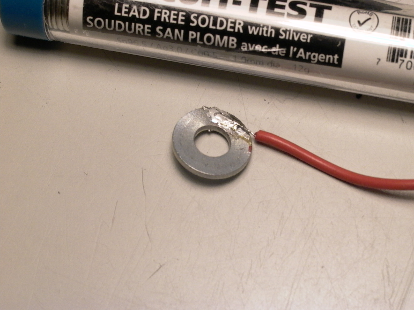
To hook up to switches, contact points were wired from the back using round connectors (I would prefer spade connectors but could not find any) (fig. 35), and the incoming path was soldered to one of the washers that make up the shaft of the switch (fig. 36). As I have not yet wound a long wave coil, one of the connectors of the band switch remains unconnected.
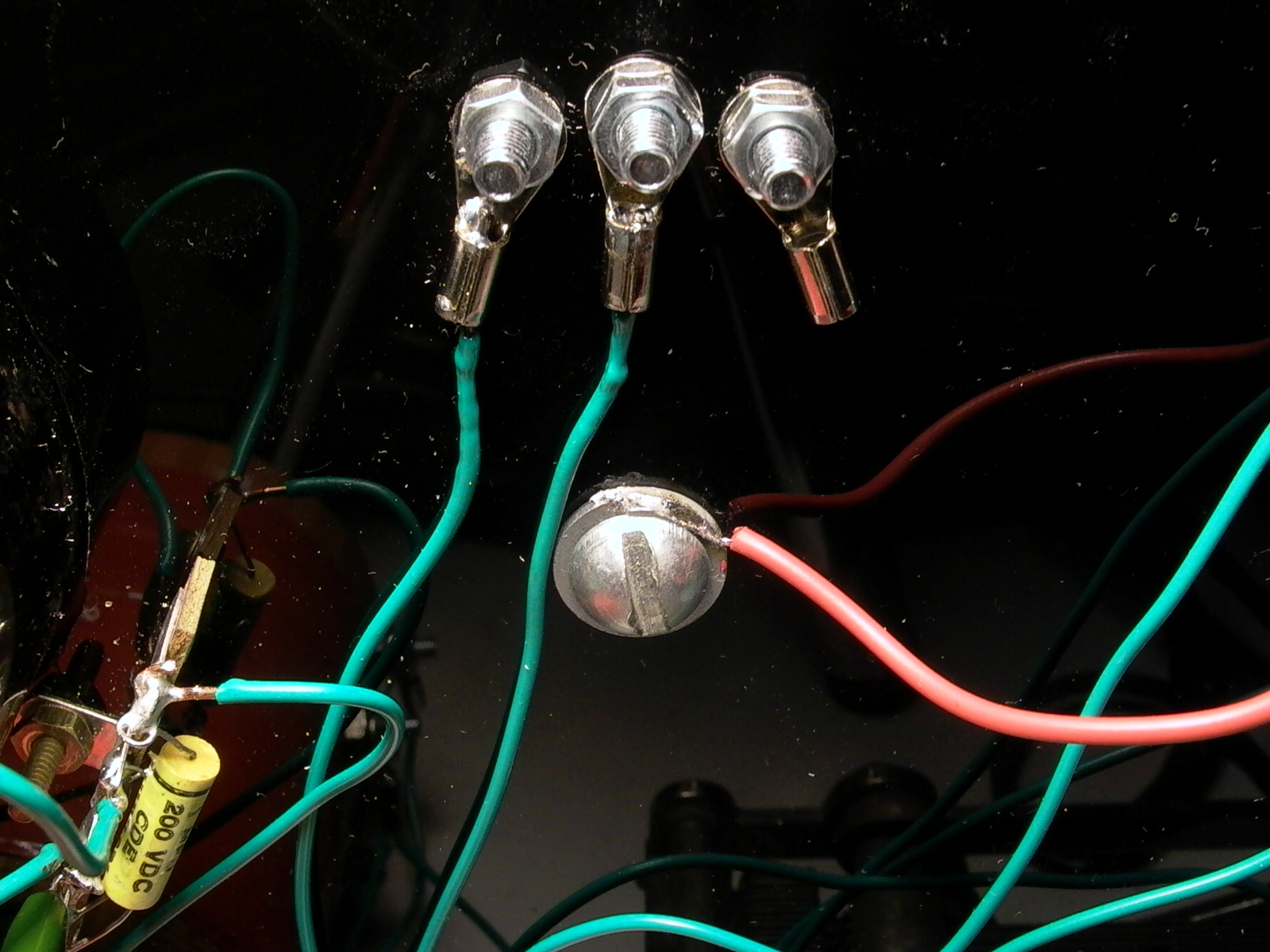
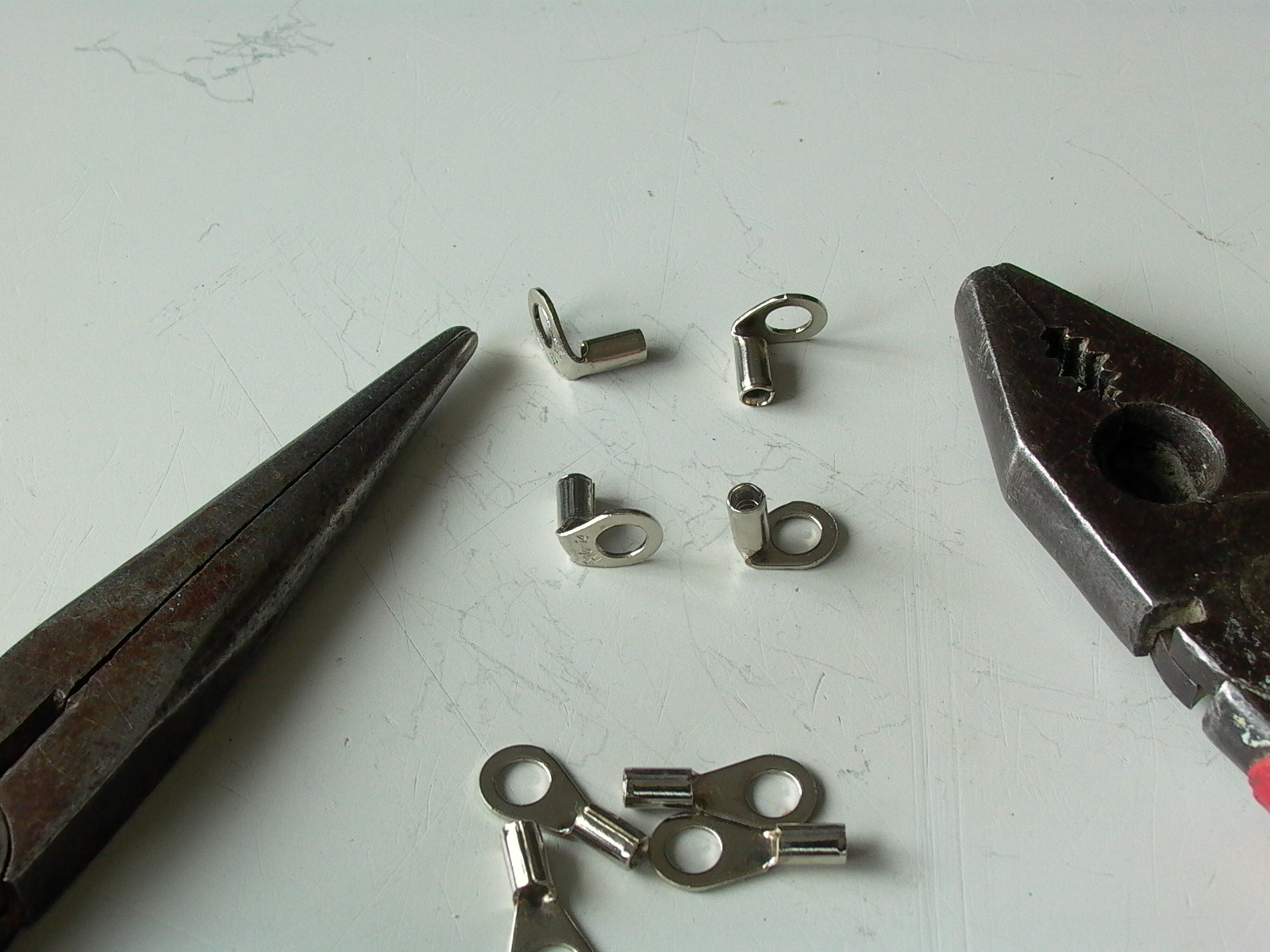
Stops were added to the end contacts of the switches. To make the stops, I used wire connectors and bent them 90 degrees with a pair of pliers and added to end contacts on the front (fig. 37 and 38).
The working circuit is now complete.
Building the Enclosure Box
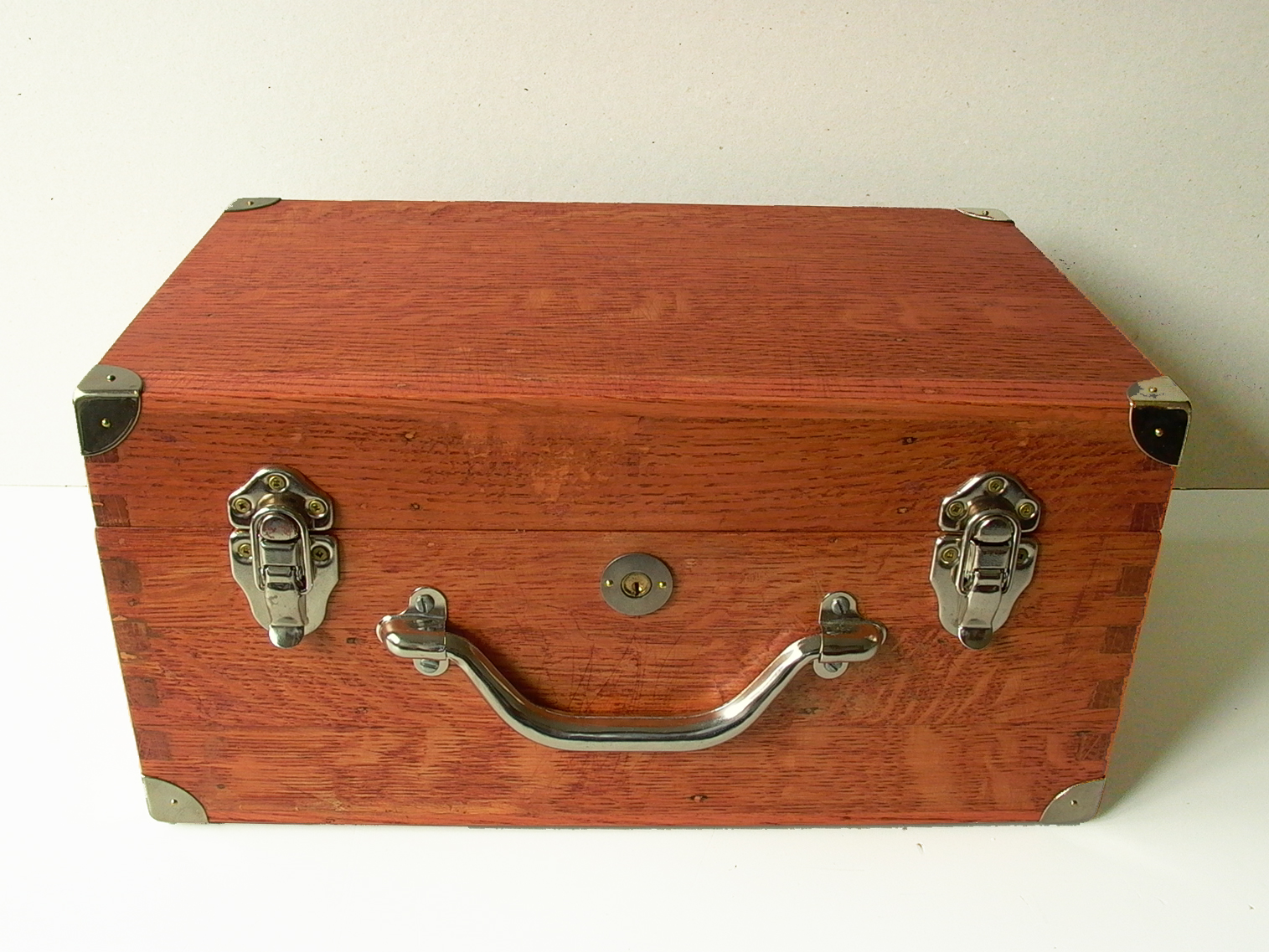
To give this crystal set an Old English style appearance, the working unit would have to be mounted in a well-finished wooden box with a lid and latch just like those of Gecophone crystal sets. As builders are encouraged to come up with other designs, this section is for inspiration only; thus, I will not indulge in fine details.
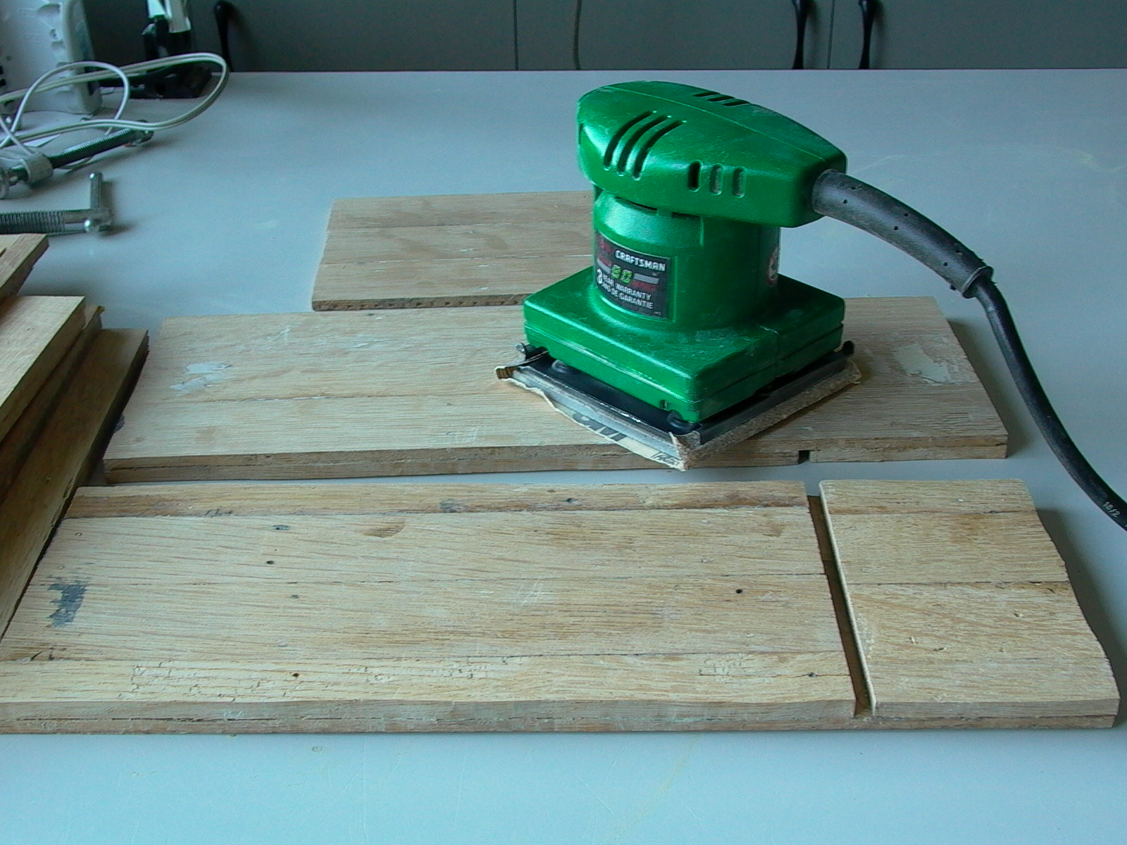
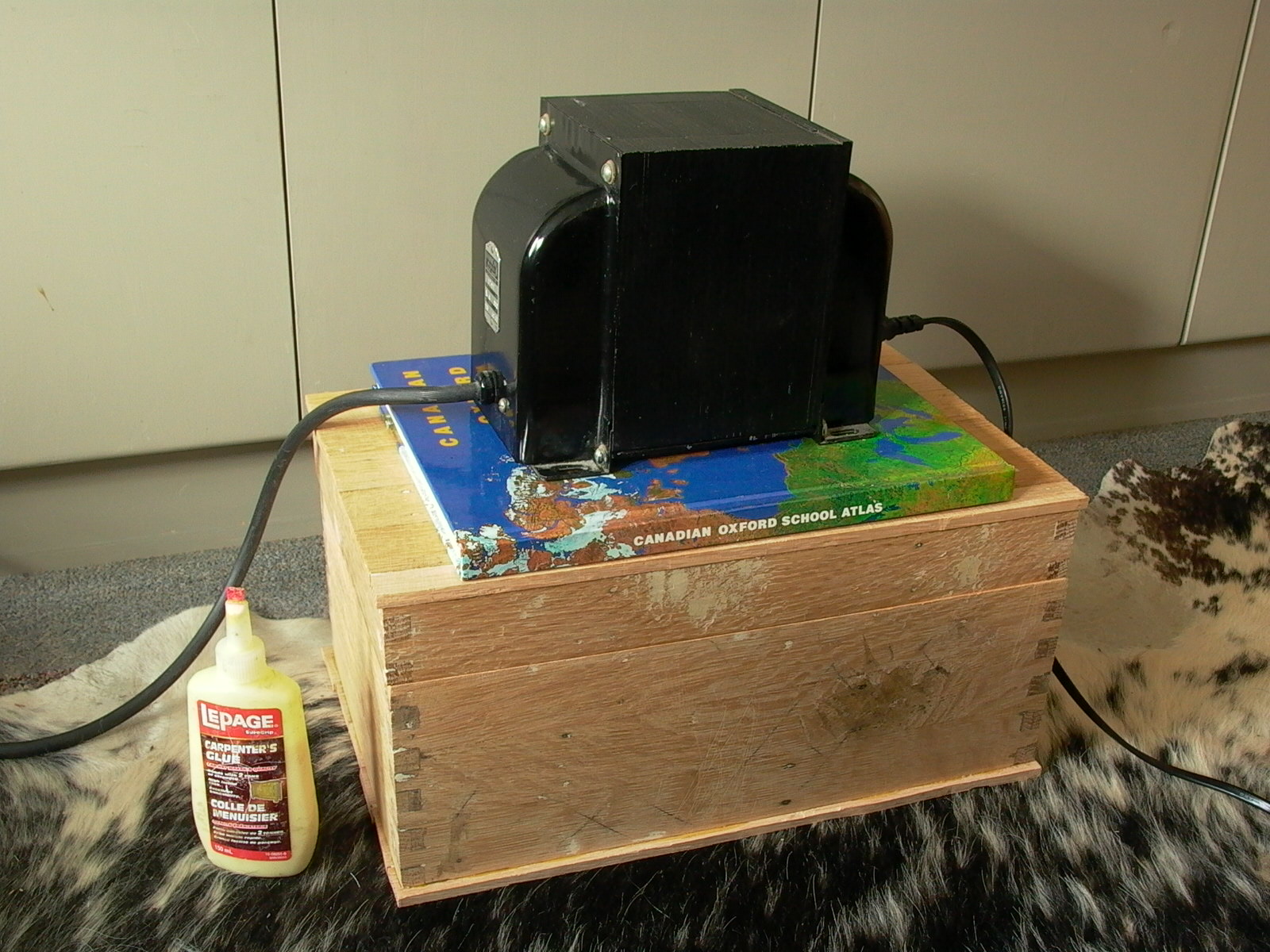
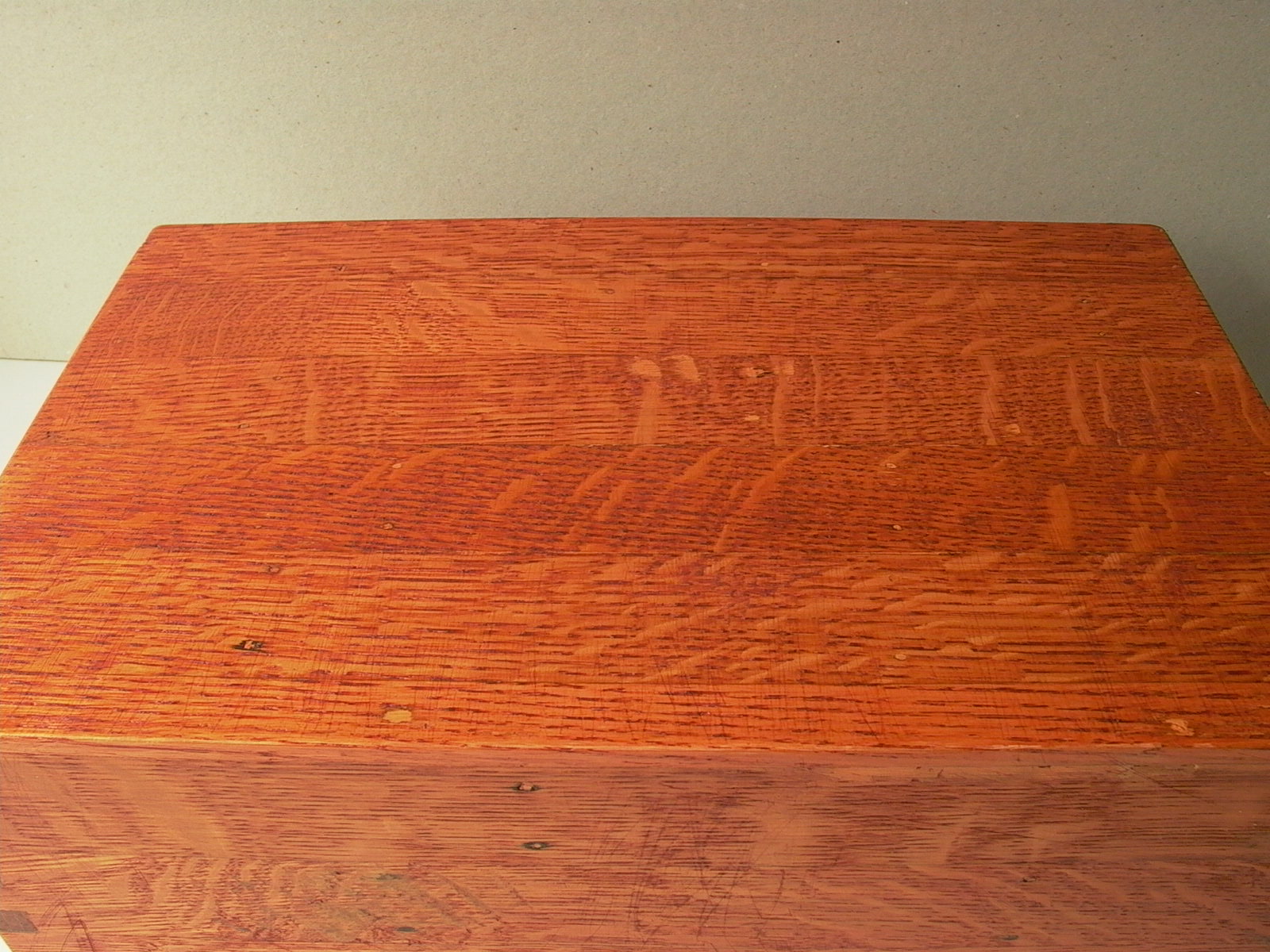
Gecophone crystal sets were originally housed in mahogany boxes. However, I was not able to source some high quality solid mahogany cheaply enough for my limited budget, and the OCD in me refused to settle for modern veneered particle board; therefore, I opted to use oak which was another material commonly used in many household and industrial products in the early 20th century as it was cheap (at the time) and usable scraps can still be had for almost nothing. In the early days, oak was usually quarter sawn (growth rings perpendicular to surface), which gives it strength and looks good too but very hard to find today and expensive. Modern oak, on the other hand, is flat/plain sawn and looks cheap, but my OCD will not settle for anything of lower quality. Then, inspired by a previous project, I came up with a solution: old hardwood floor strips glued together.
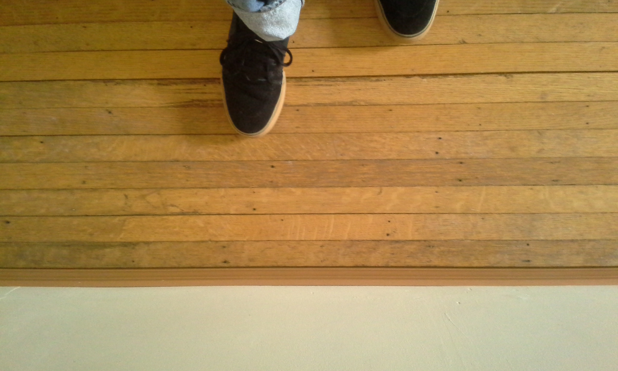
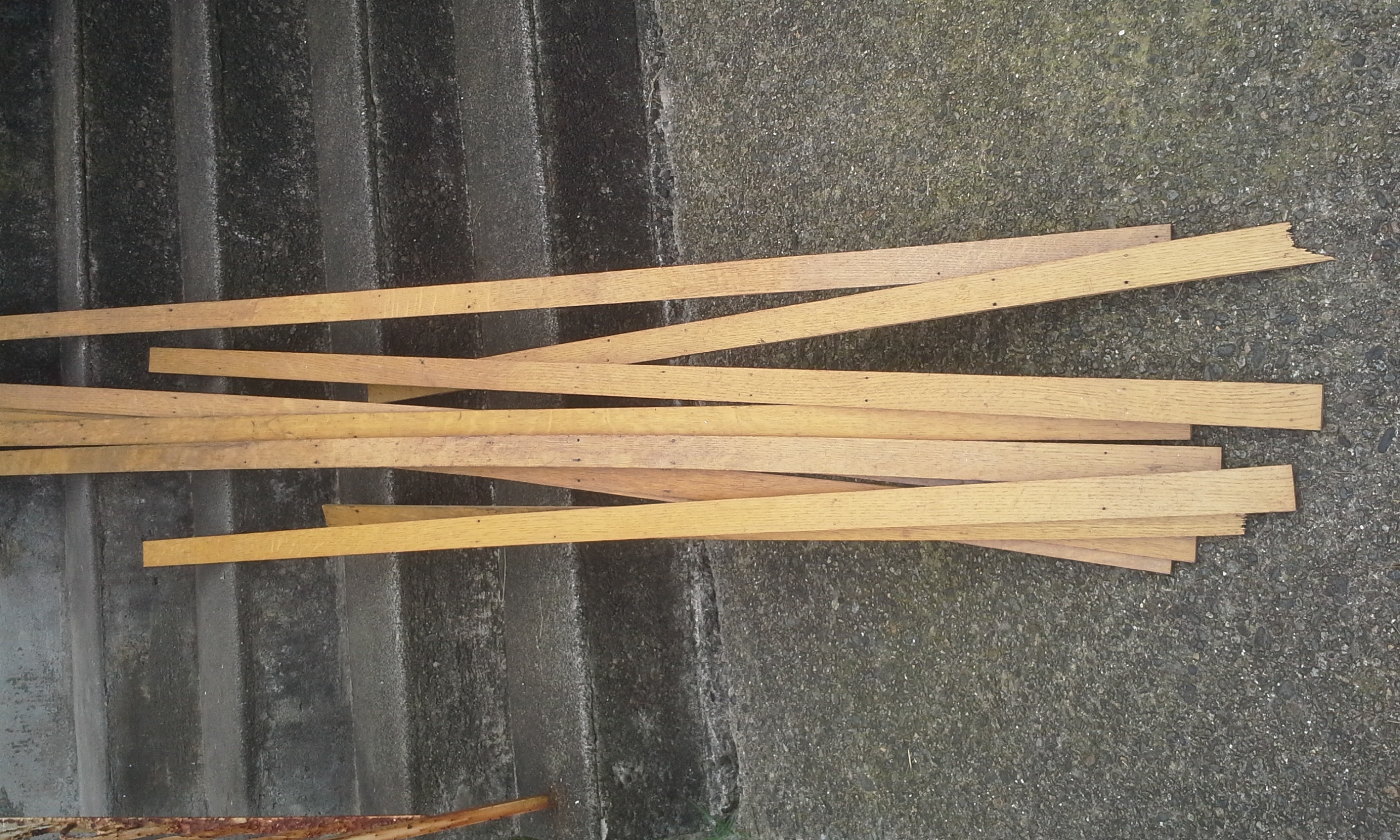
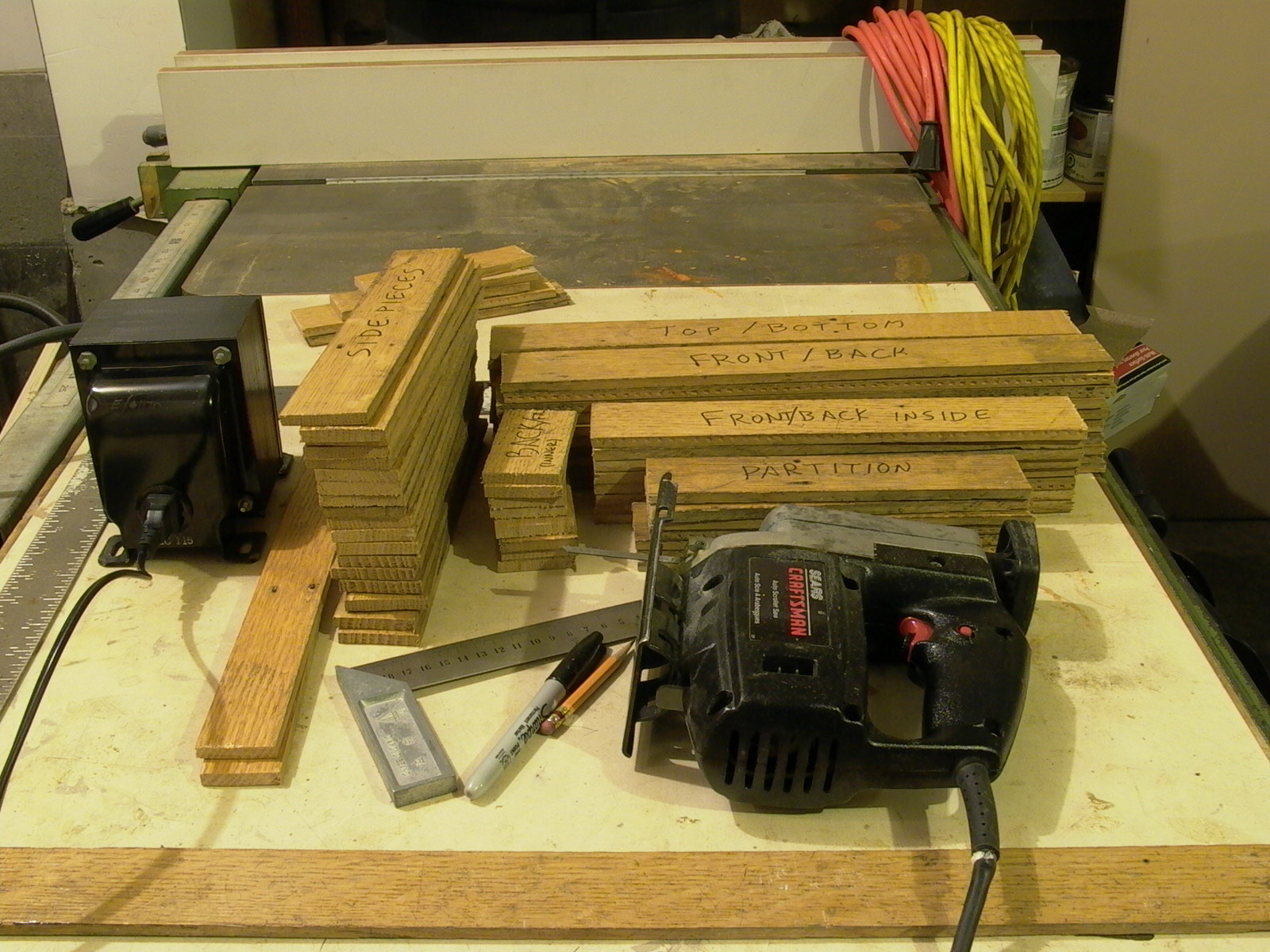
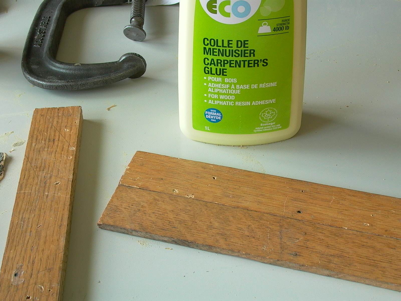
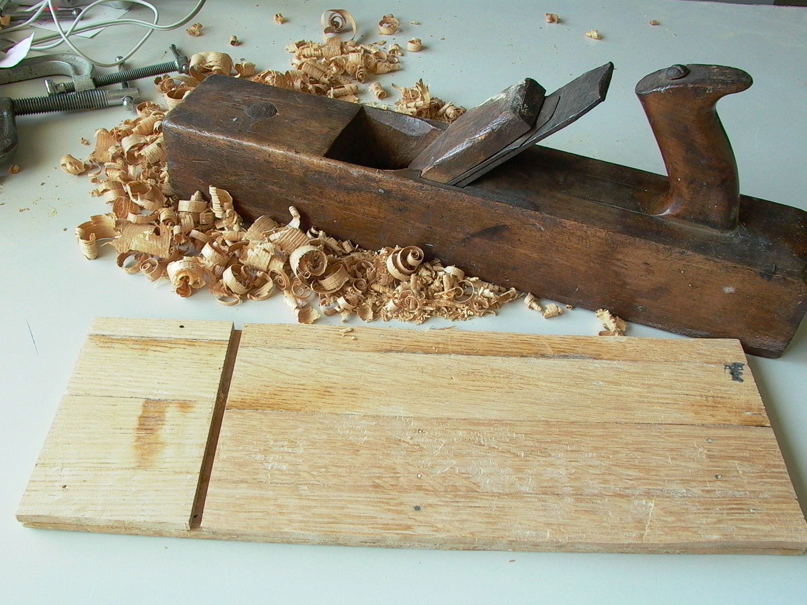
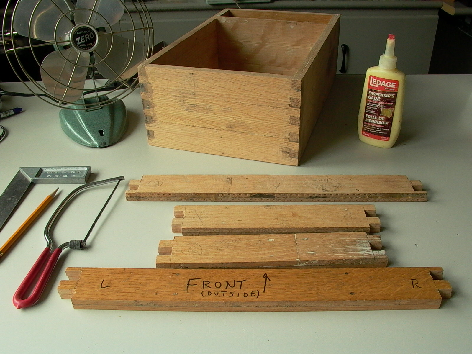
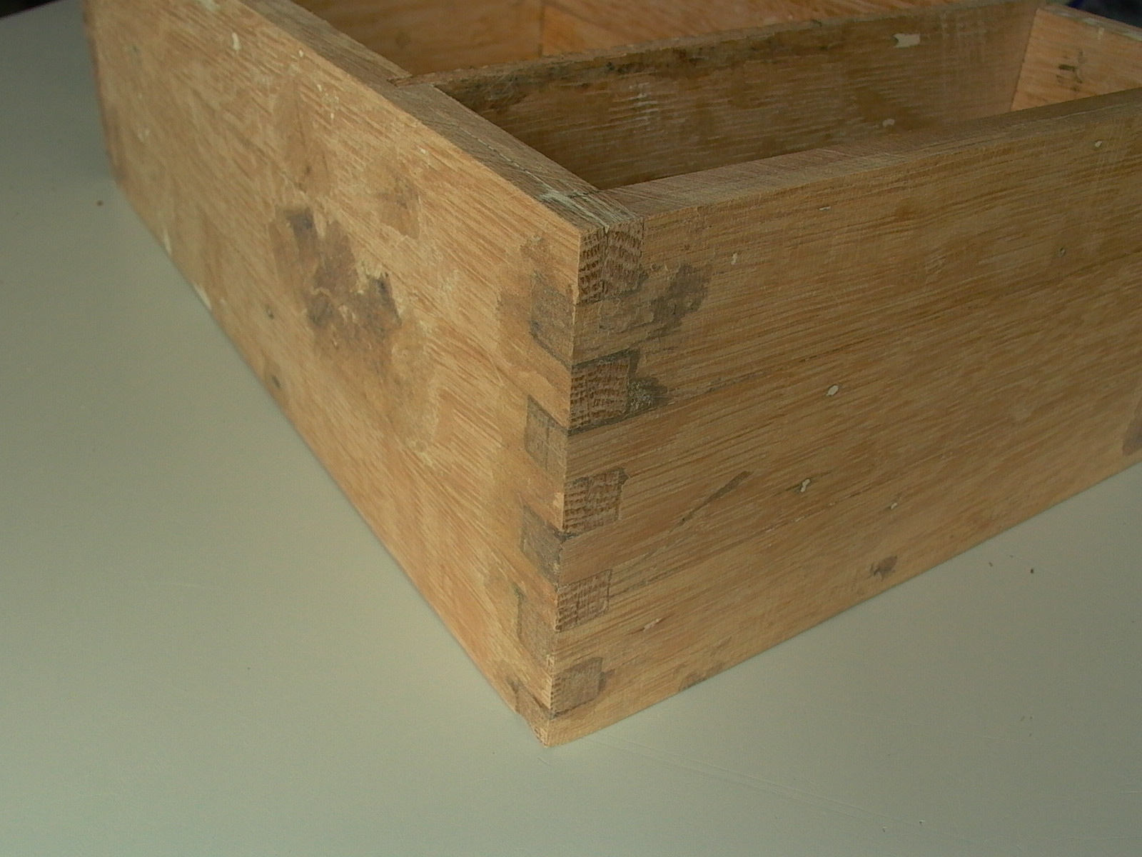
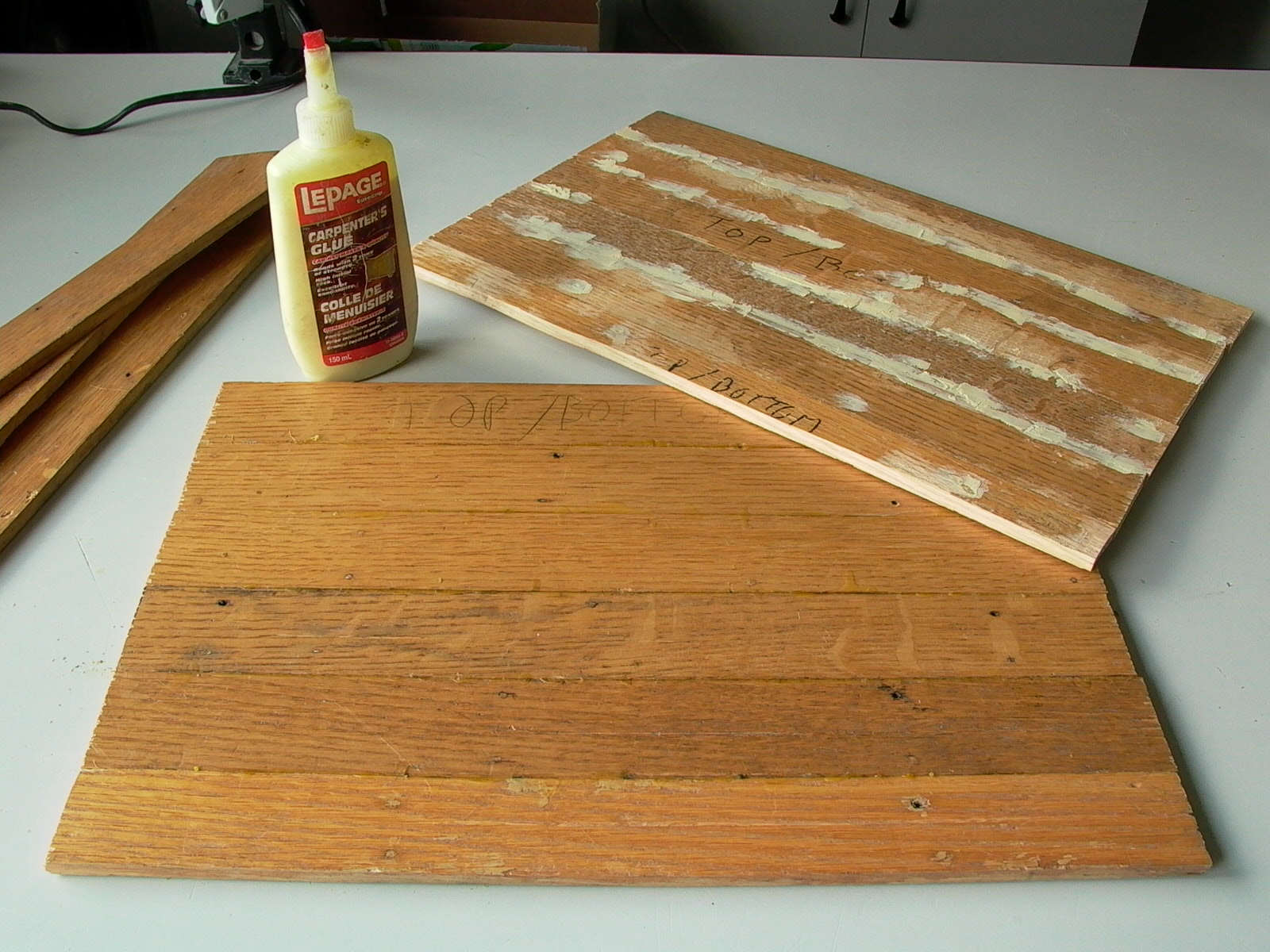
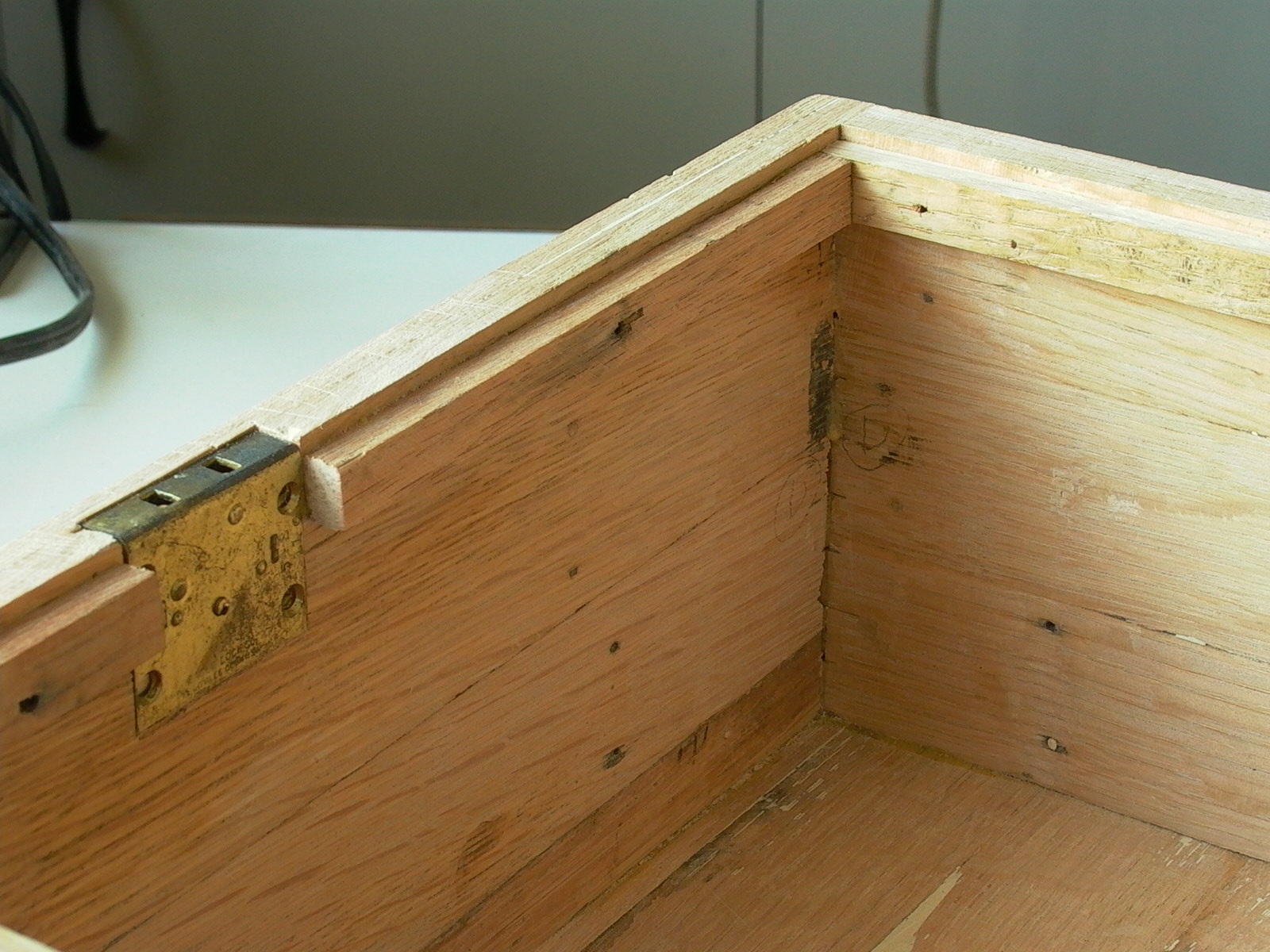
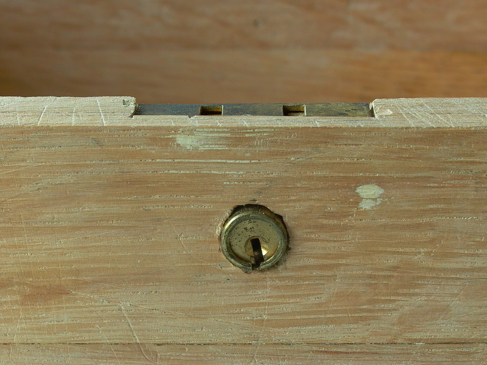
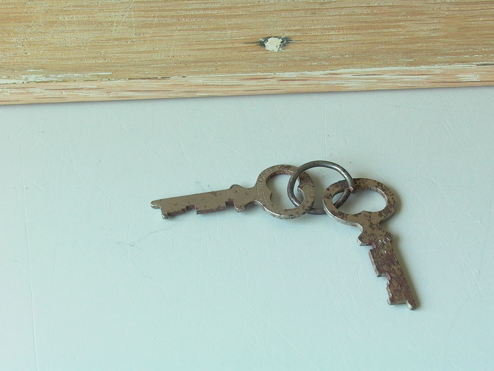
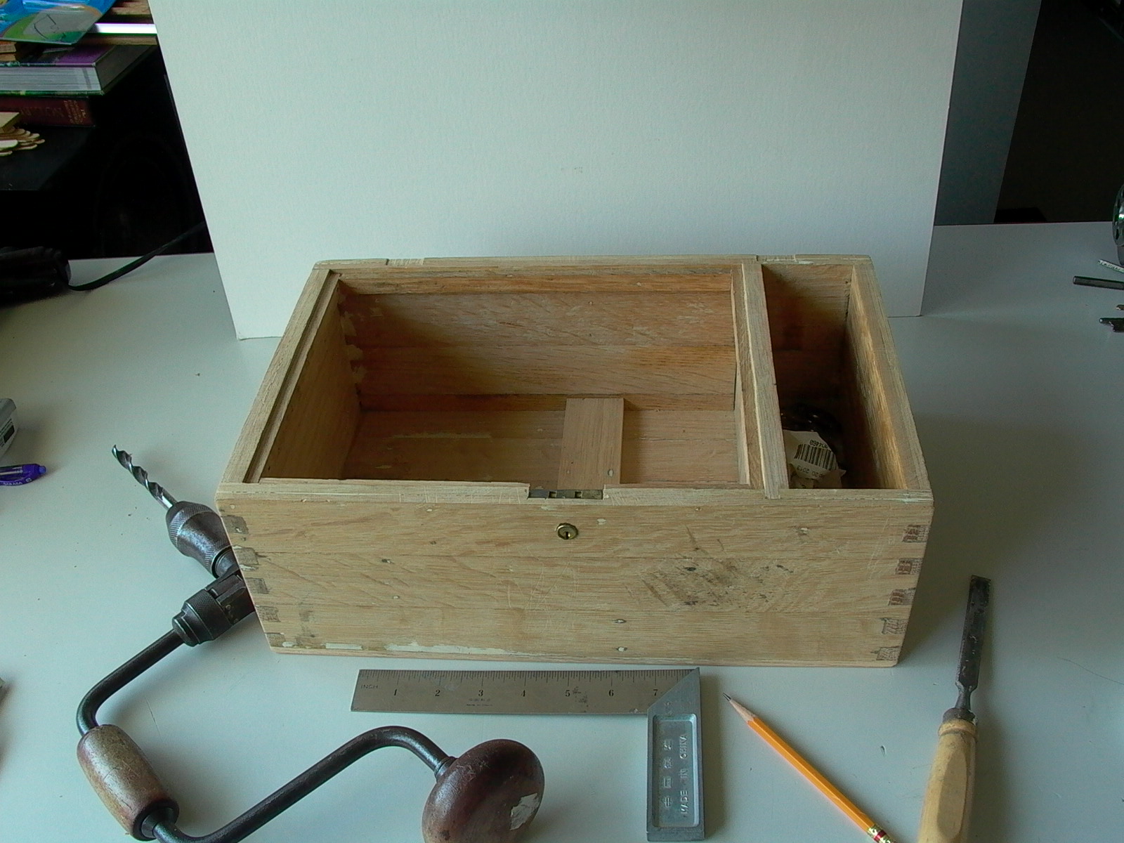
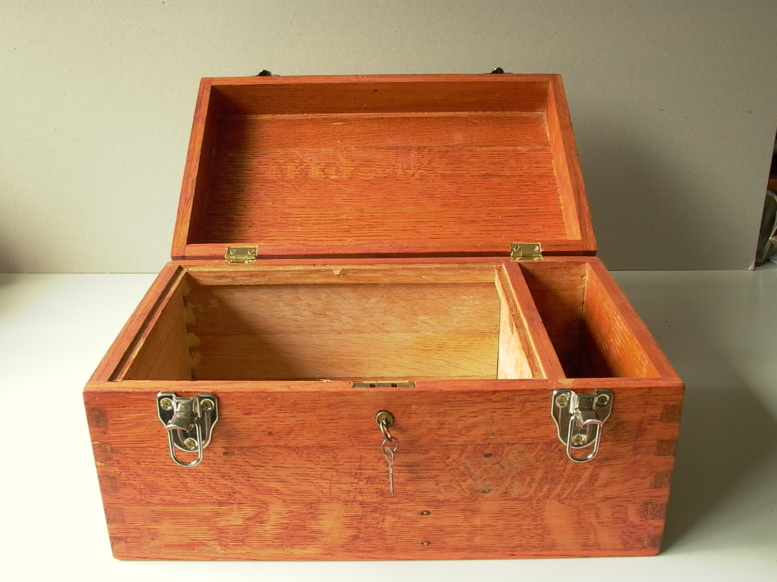
I went to a near by demolition salvage store and purchased a bundle of oak hardwood flooring strips (above/fig. 39 and 40). These were very common in many homes from the 1930’s to the 1950’s, have quarter sawn surfaces, and are reasonable priced. Once I transported the materials home safely, strips were cut to required lengths and built up to required thicknesses and widths (fig. 41), then planed (fig. 42) and rough sanded (fig. 43). Corners were joined with finger joints (based on, but often incorrectly called “dovetail” joints); although finger joints are meant to be cut by machine using a special saw jig (as opposed to dovetail joints which are traditionally cut by hand), I did the ones on my box painstakingly by hand (fig. 45 and 46). The four sides of the box were made from two layers of 1/4″ thick flooring strips while the top and bottom were composed of a single layer (figure 47 to 49). Note the partition in the box (fig. 53): the large compartment will contain the radio while the smaller compartment will hold the headset. An inner ledge was added around the main compartment to hold the panel of the crystal set, hinges were added (not shown), and a new-old-stock antique Eagle (brand) piano lock was installed (figures 50 to 53).
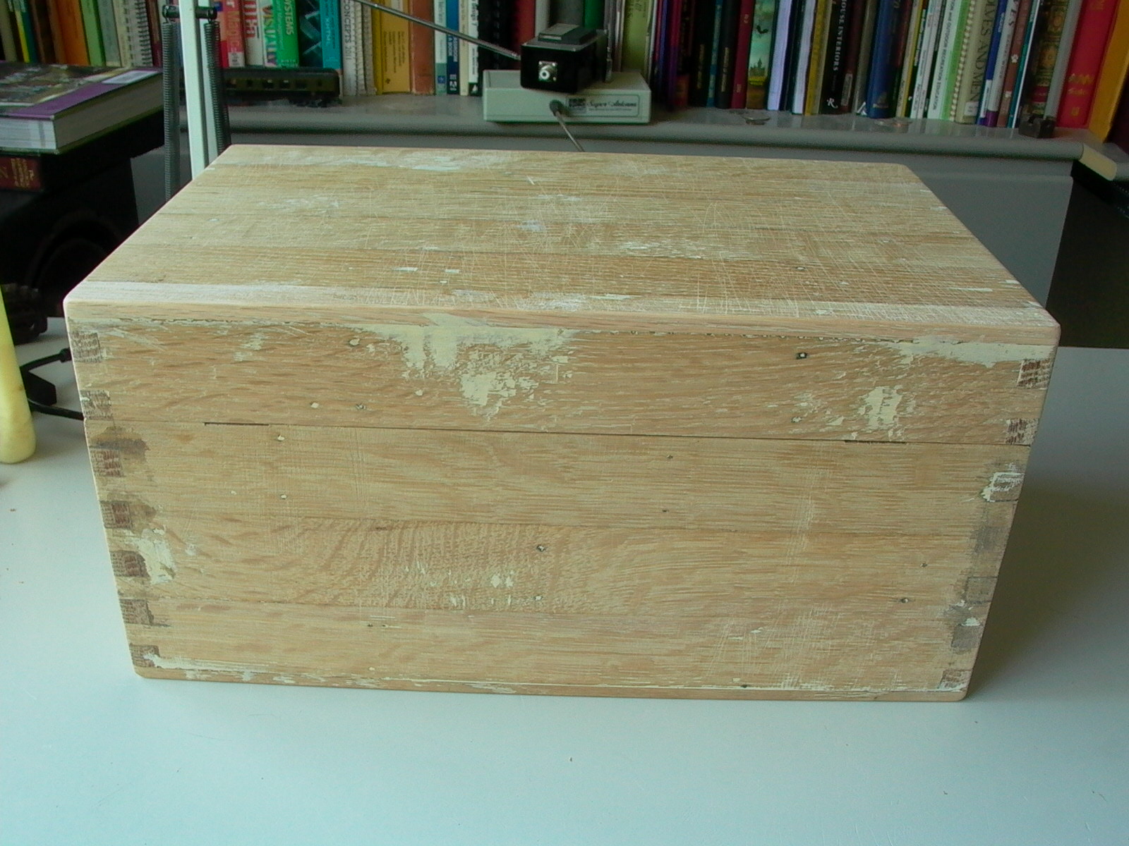
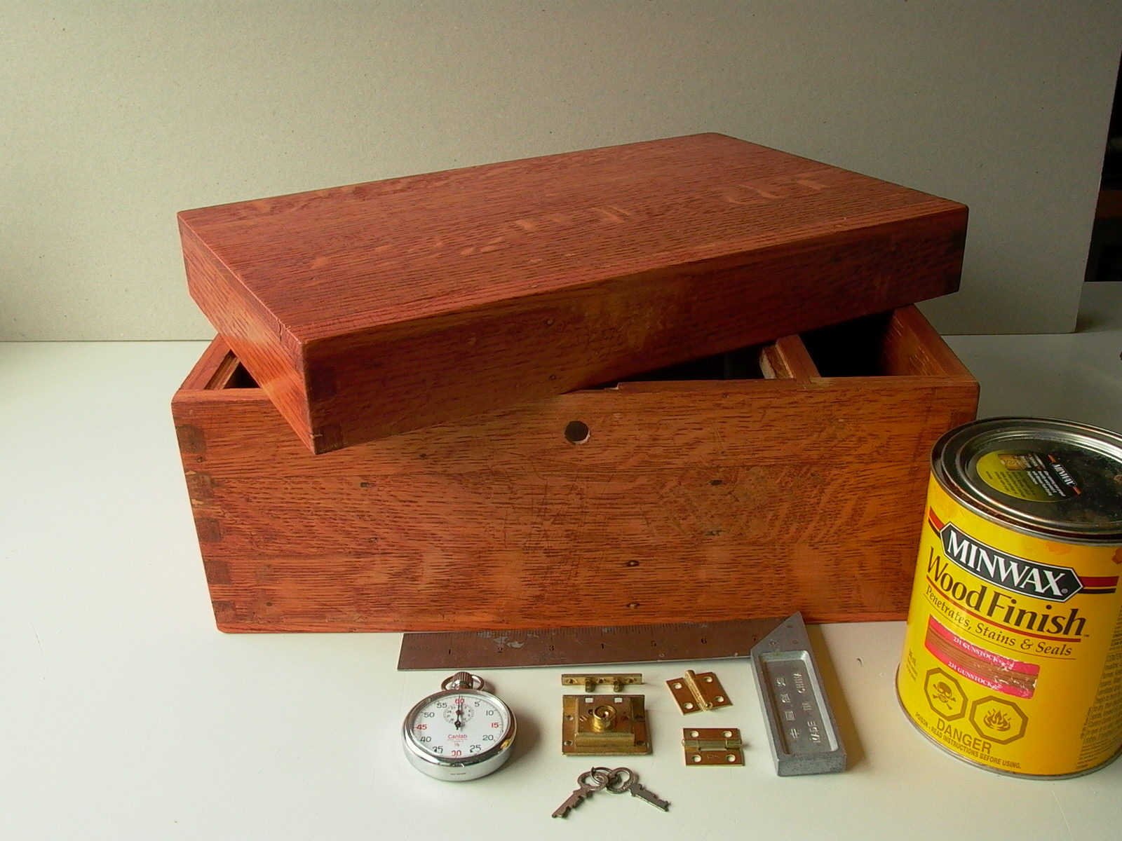
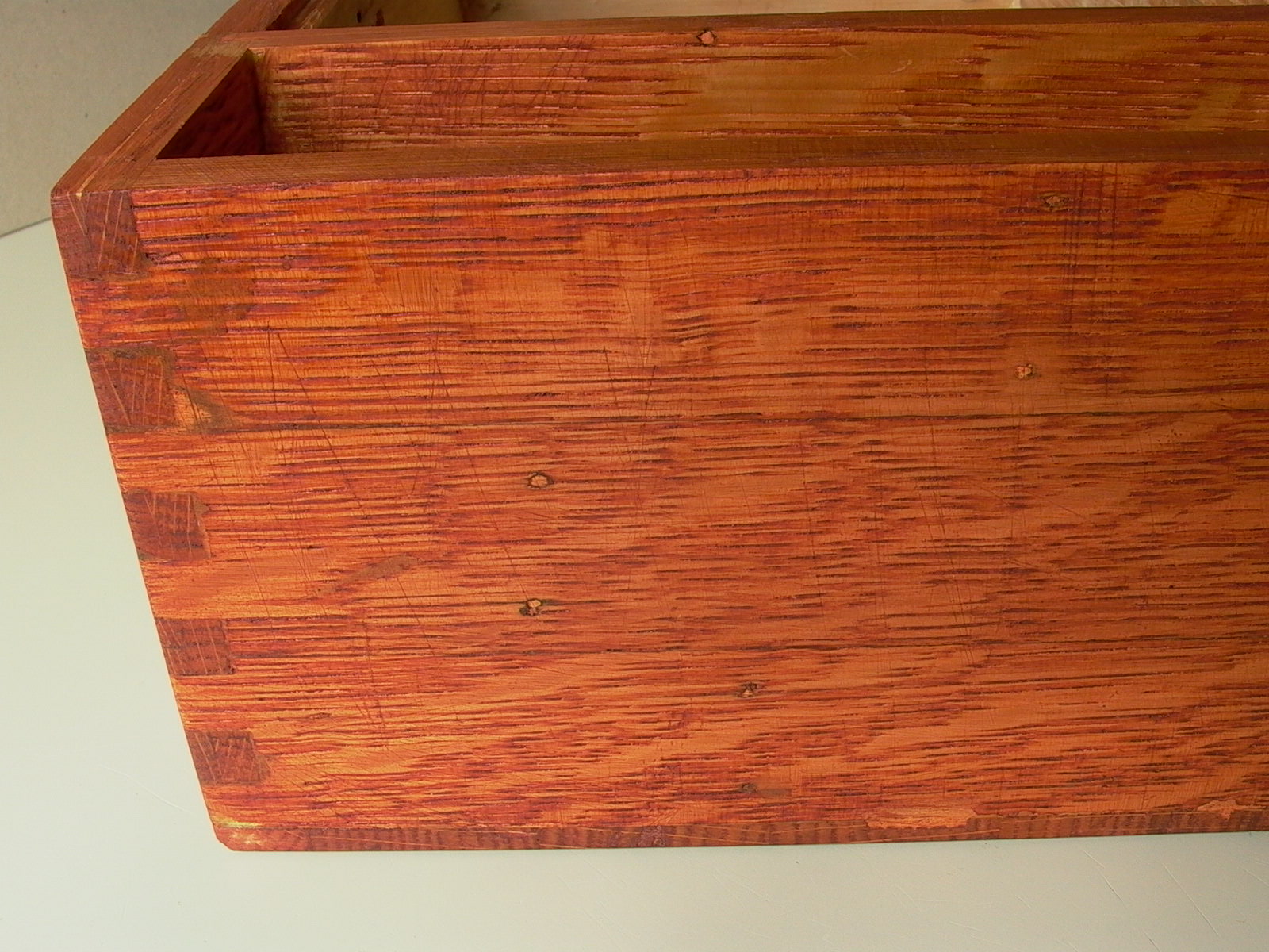
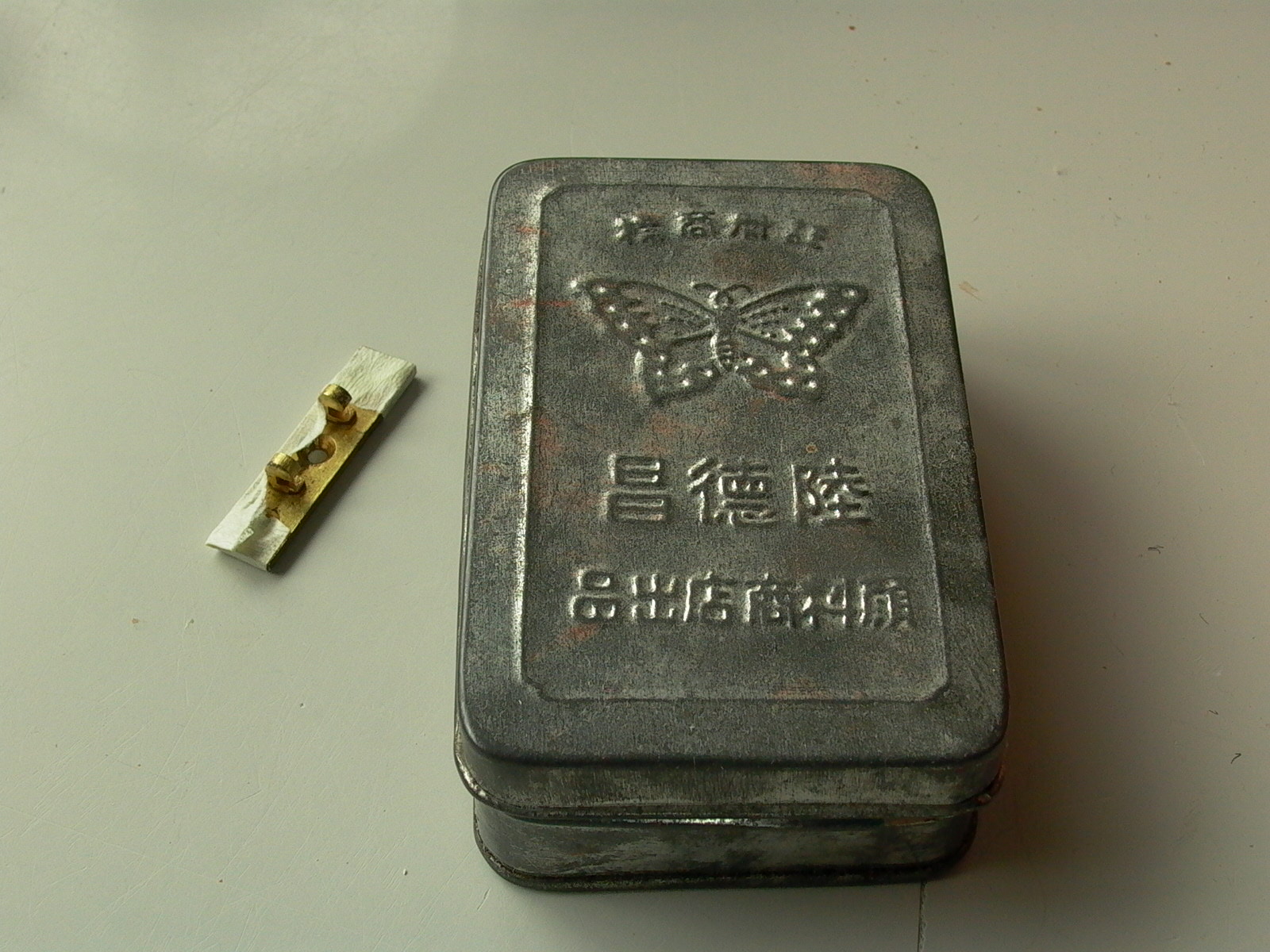
The hardware was then removed and the box was sanded and finished with Minwax “Gunstock” colored stain according to instructions (below/figures 54 to 56), and covered with varnish. When the final coat of protective varnish had dried, the hinges, piano lock, and toggle latches were reinstalled (fig. 57).
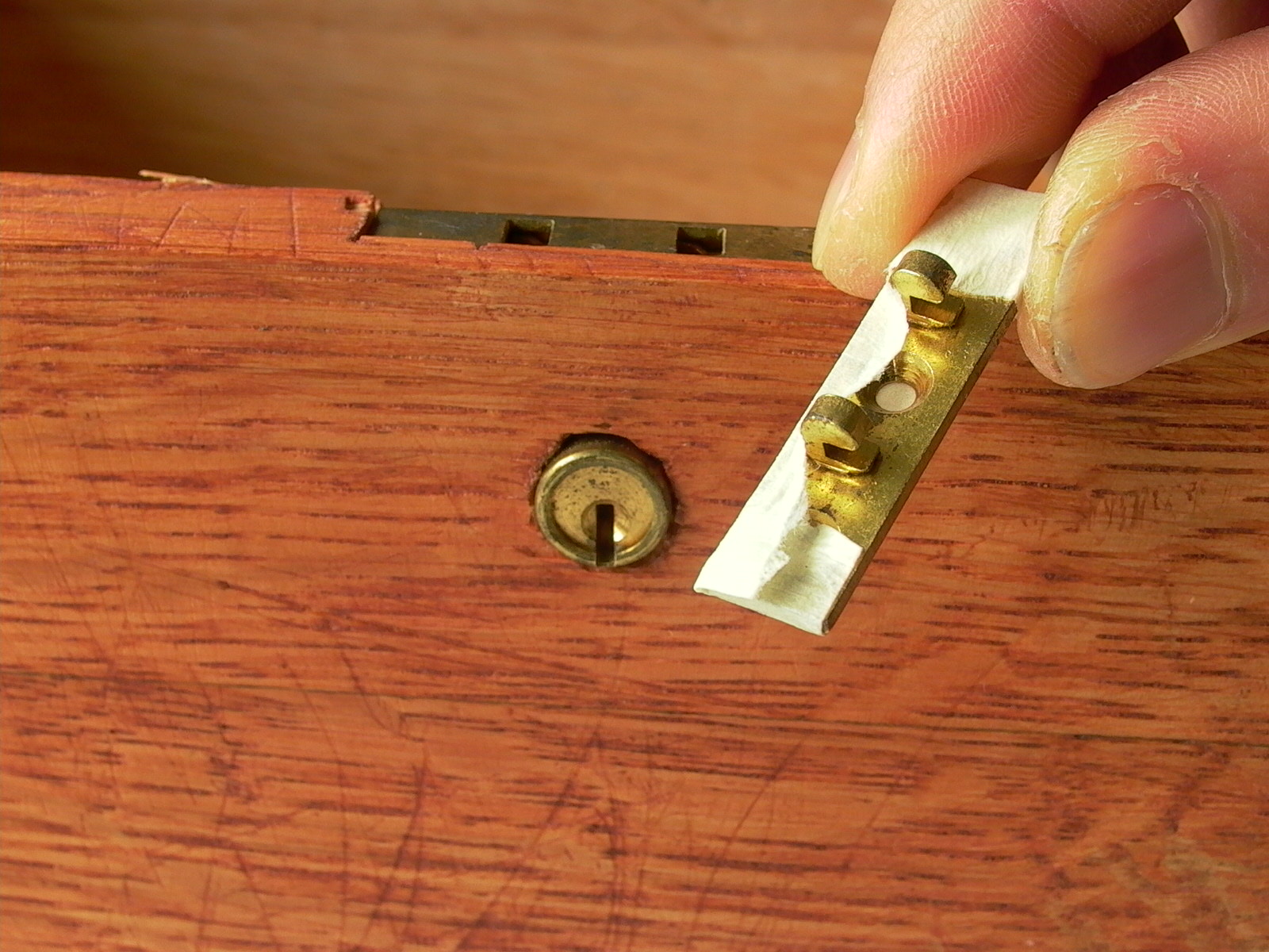
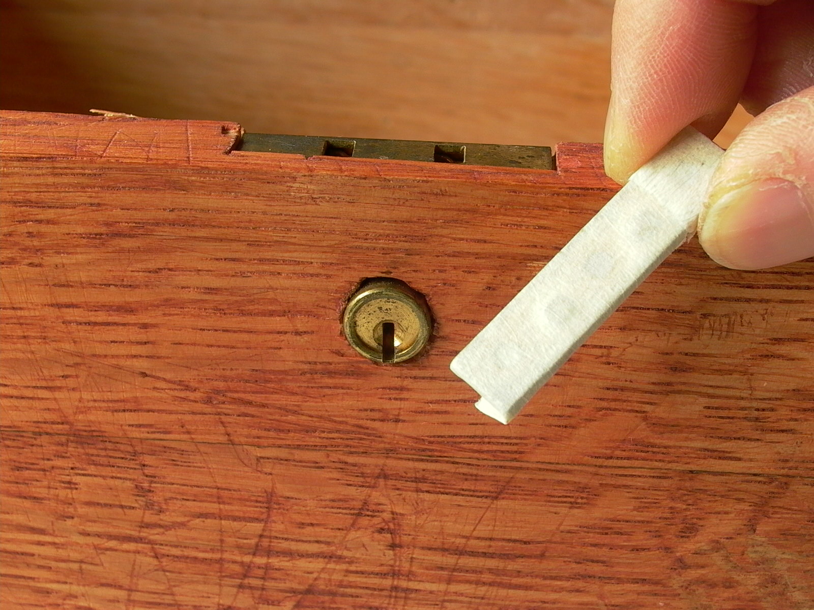
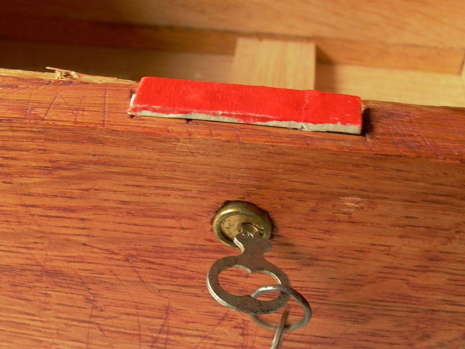
In order for the lock to work, the link plate had to be installed. For some reason, positioning bolt holes and strike or link plates is a difficult task for many. One hack to get around this is to put an ink pad on the bolt of a lock (a user on Reddit who knows about this hack recommends using old lipstick) and let the bolt stamp a mark with the door closed. In this case though, the lock has holes into which hooks on the link plate enters when the lid closes. So, one side of the plate was covered with masking tape and covered with red Chinese ink (used in the Orient by artists and poets for signature stamps), then with the hooks inserted into the lock, the lid was closed down, stamping a mark on its edge. The stamped area was then planed with a chisel and link plate was installed when sufficiently deep enough (figures below/fig. 58 to 61).
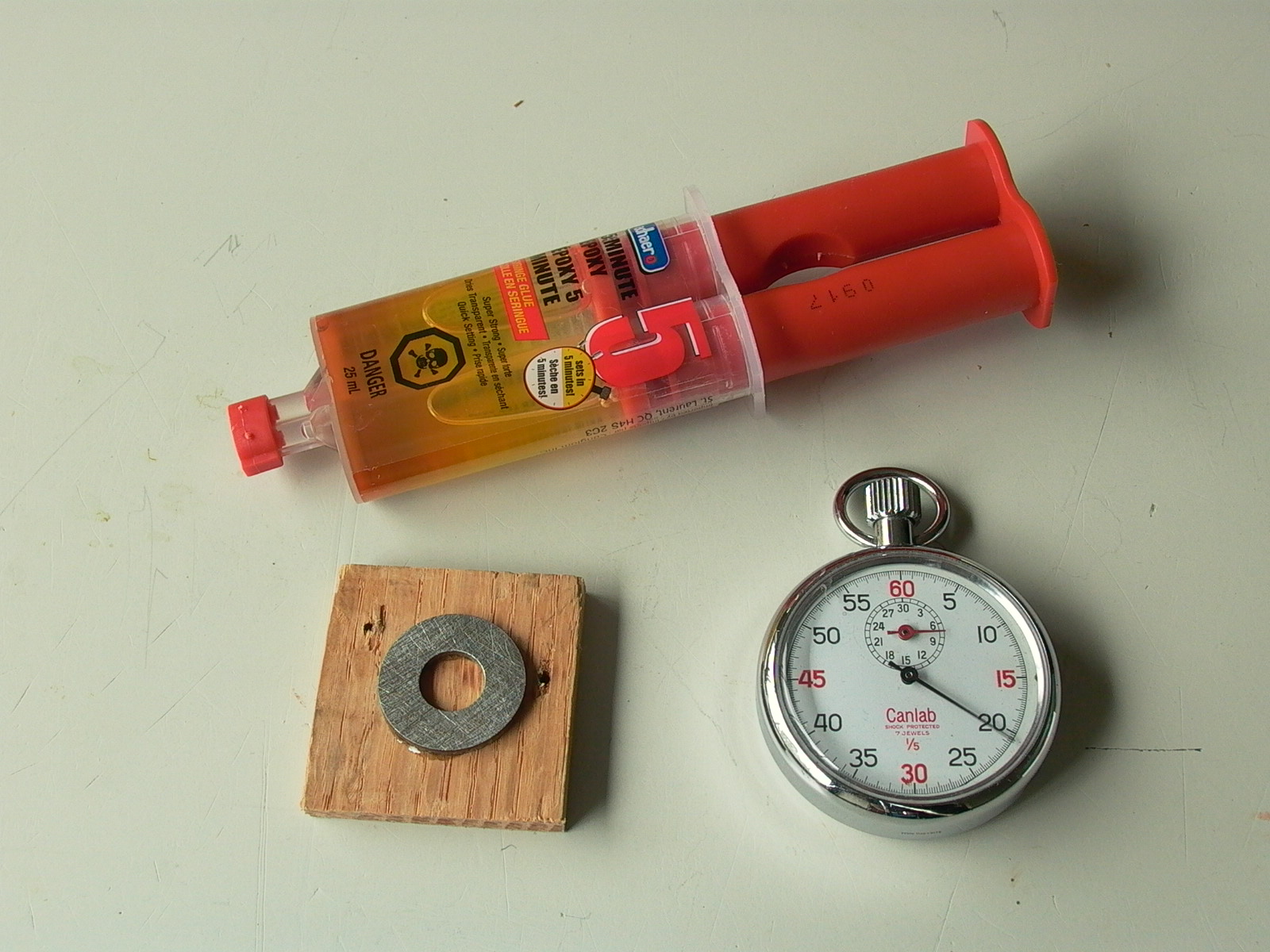
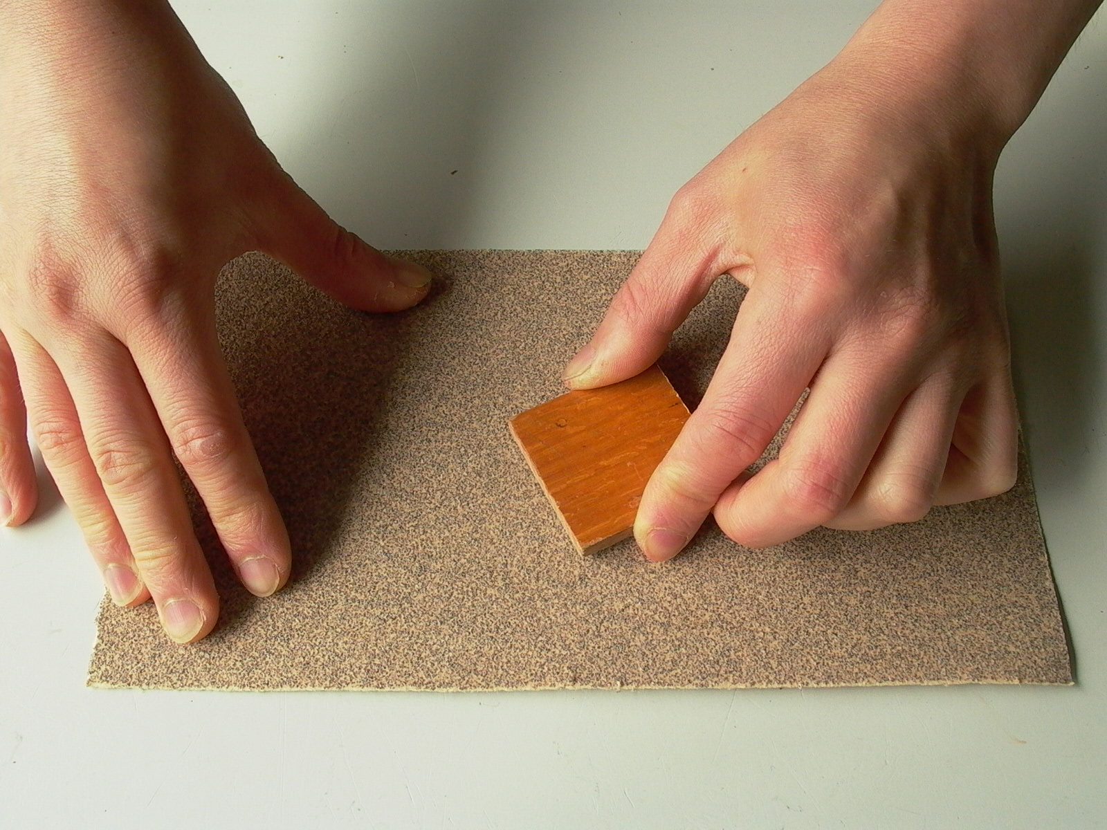
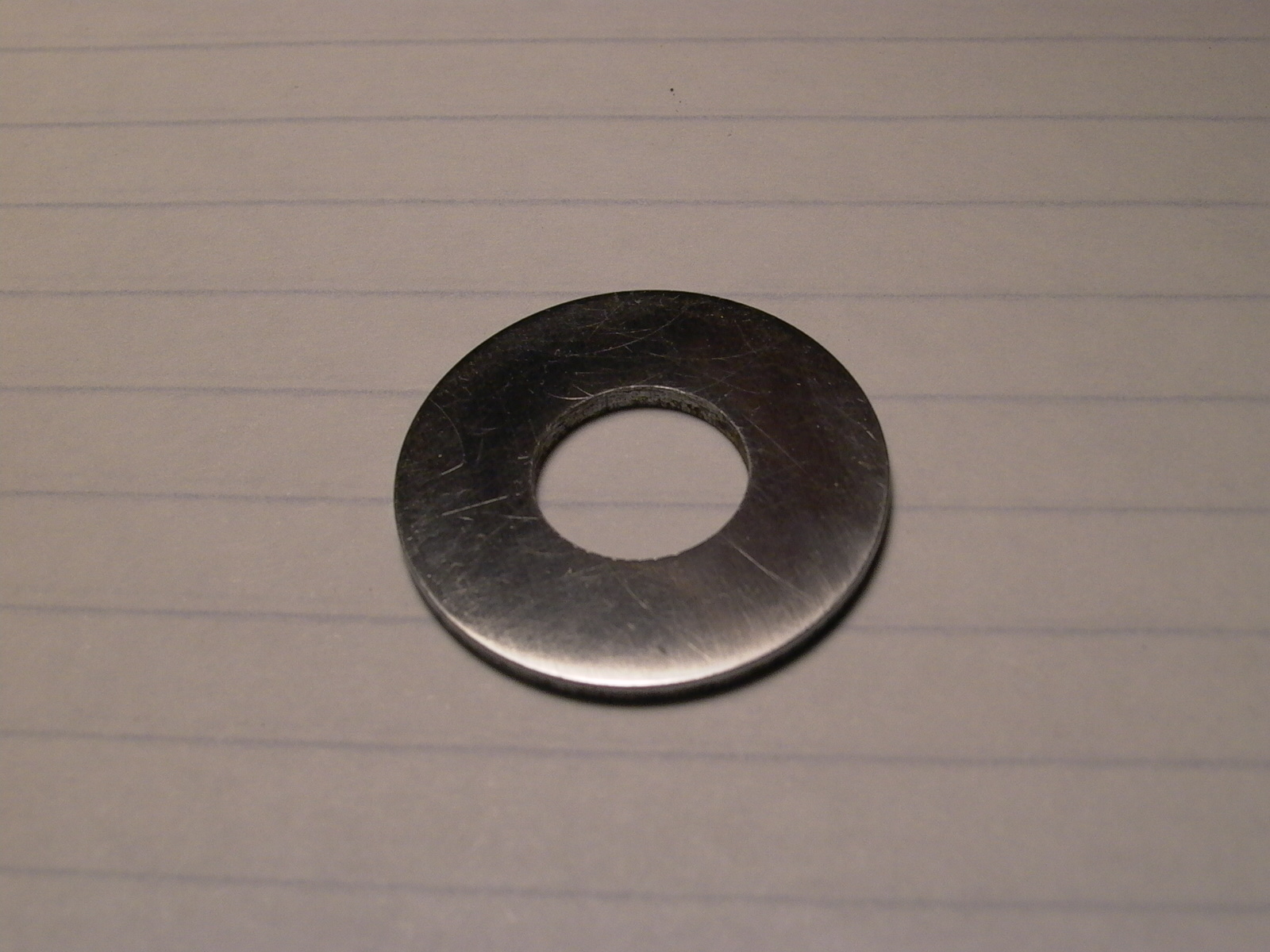
Because the hole for the tube of the lock was uneven (another OCD nightmare), an escutcheon was needed for the keyhole. However, plates for this type of keyhole are difficult to come by so one would have to be fabricated from a washer. A washer with a hole close to the diameter of the keyhole tube was used for this purpose (figure 62). As it was a little too thick, it needed to be sanded. In order to be able to hold the washer for sanding, the washer was glued to a scrap piece of wood (leftover hardwood flooring) with two-part epoxy glue (fig. 63). The washer was first sanded with 60 grit, then 80 grit as it was approaching desired thickness, followed by 120 grit, 600 grit, and finally 800 grit (fig. 64). At this point, the surface was smooth and shiny; the photo (fig. 65) does not do it justice but I can assure the reader that is a very smooth finish.
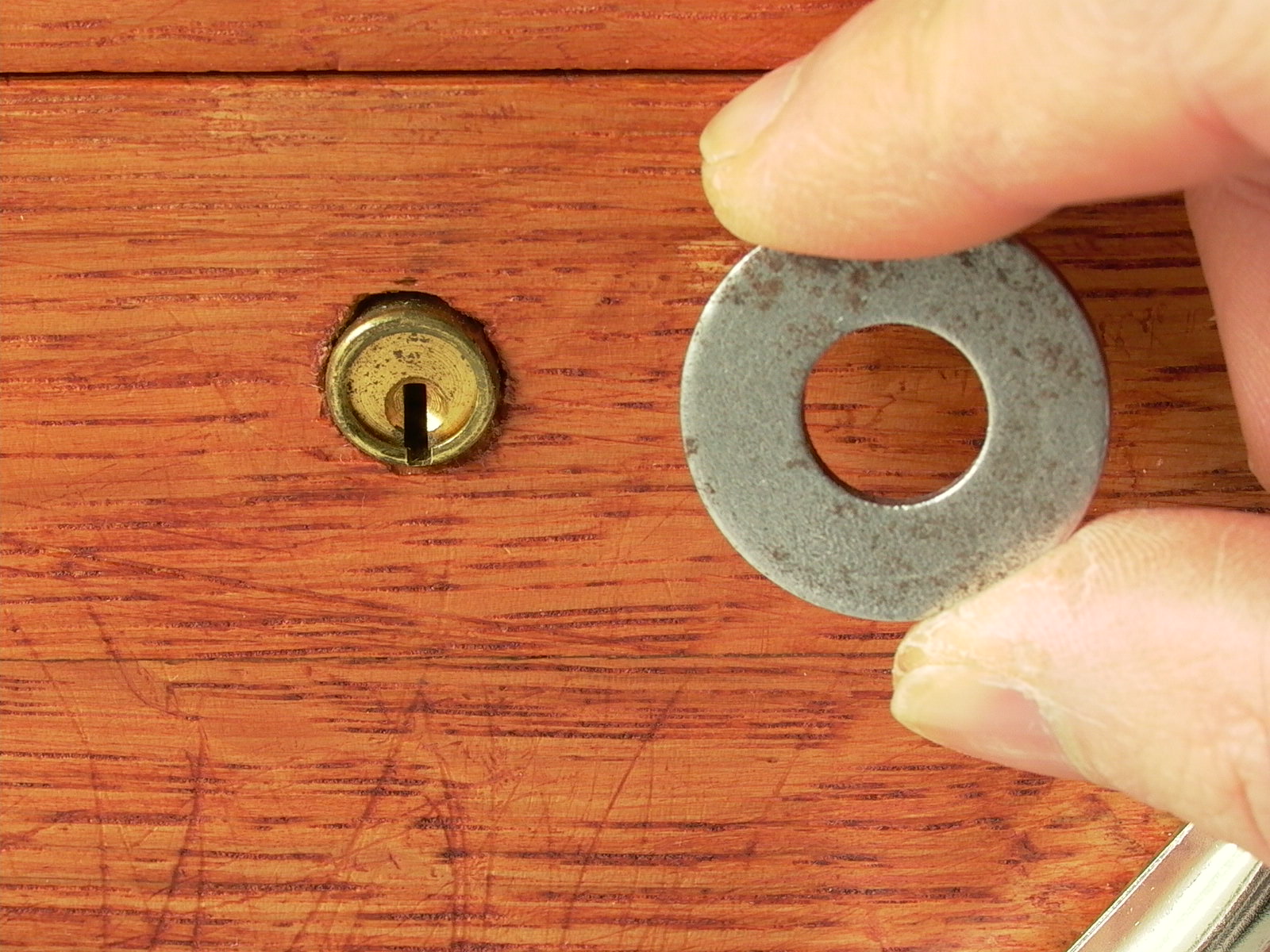
The center hole was then widened by about a fraction of a millimeter in order to allow the cylinder of the lock to fit. This was achieved by wrapping a strip of 60 grit sandpaper around my pinky finger, then placing my finger in the hole and giving the washer about 5-6 complete turns after which, the key tube was able to fit.
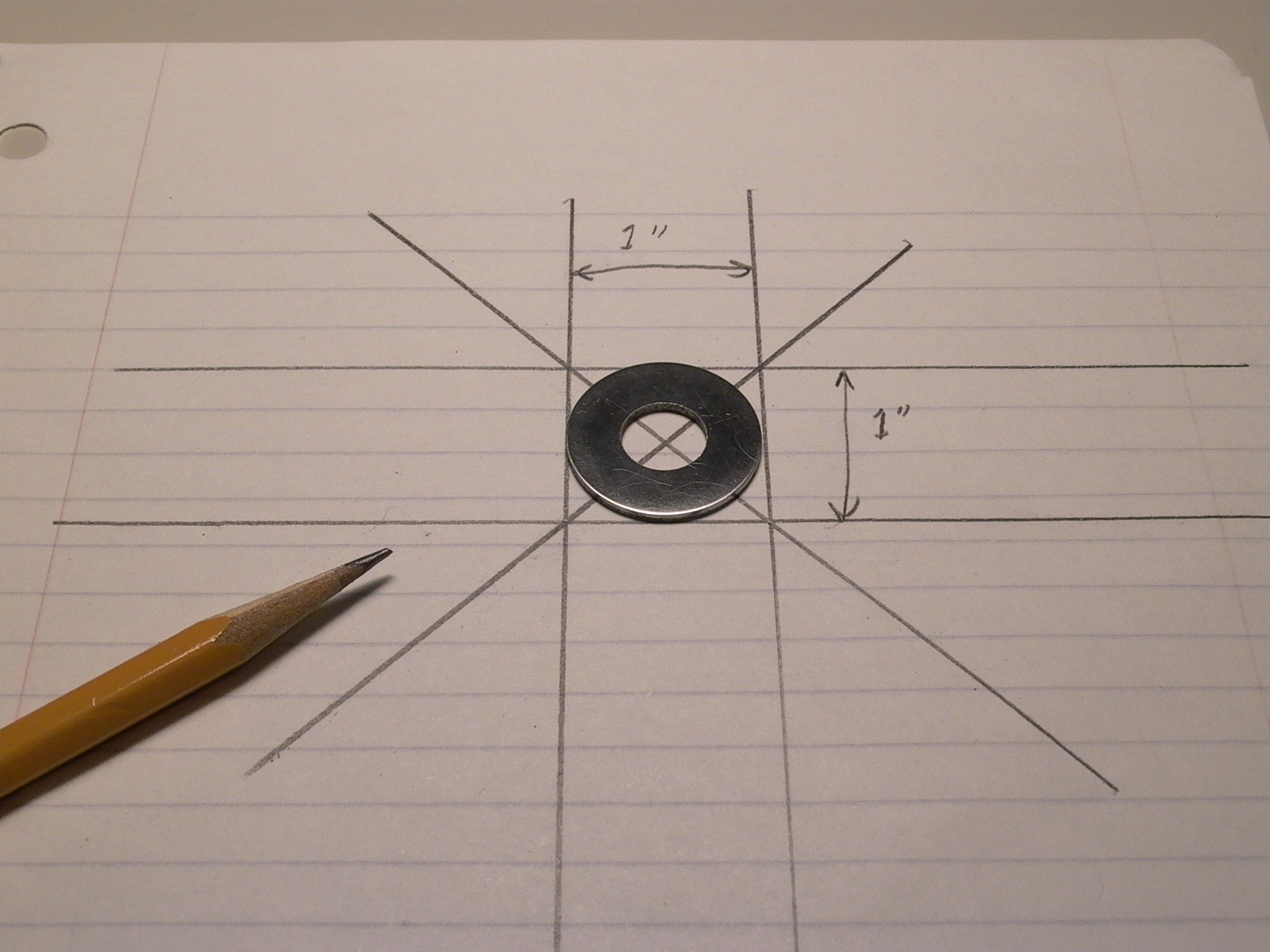
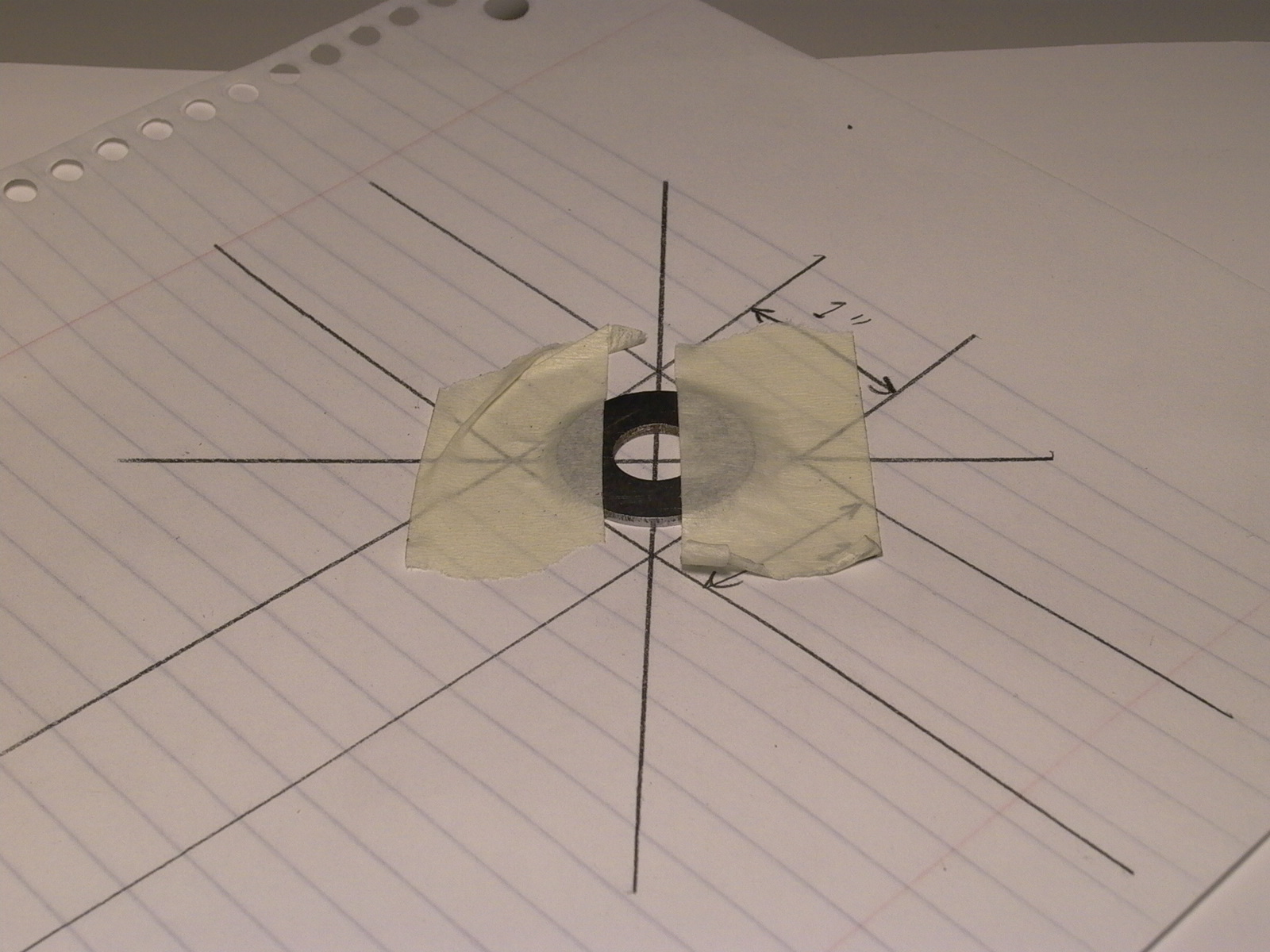
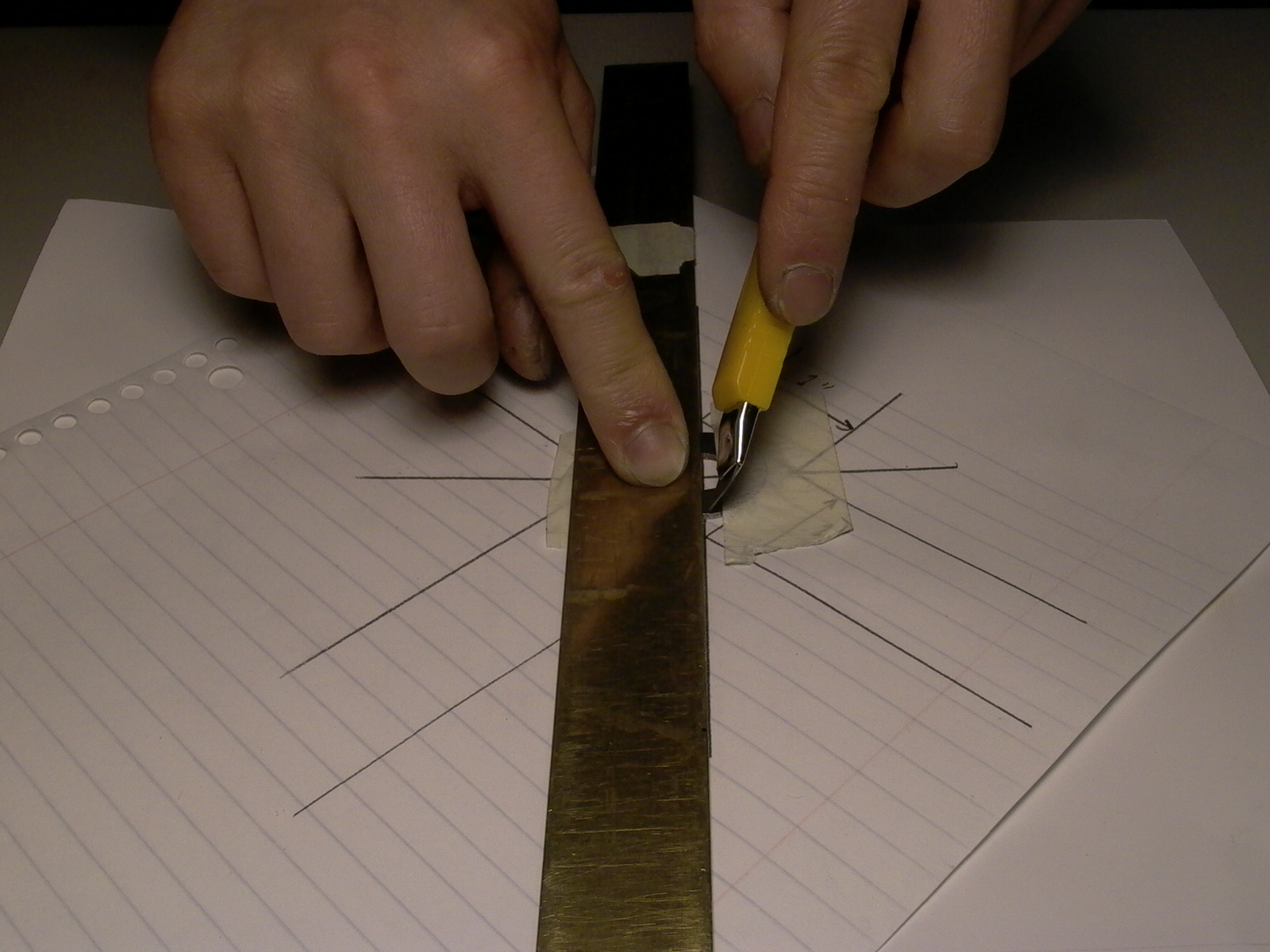
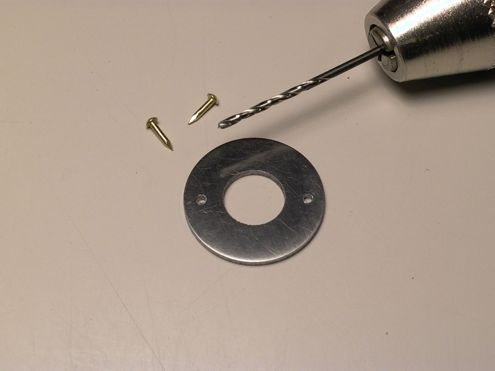
To find and mark the positions of the pinholes, geometry was used to find the center line and a knife was used to scratch the marks on the rough side of the washer (figures below/fig. 66 to 69).
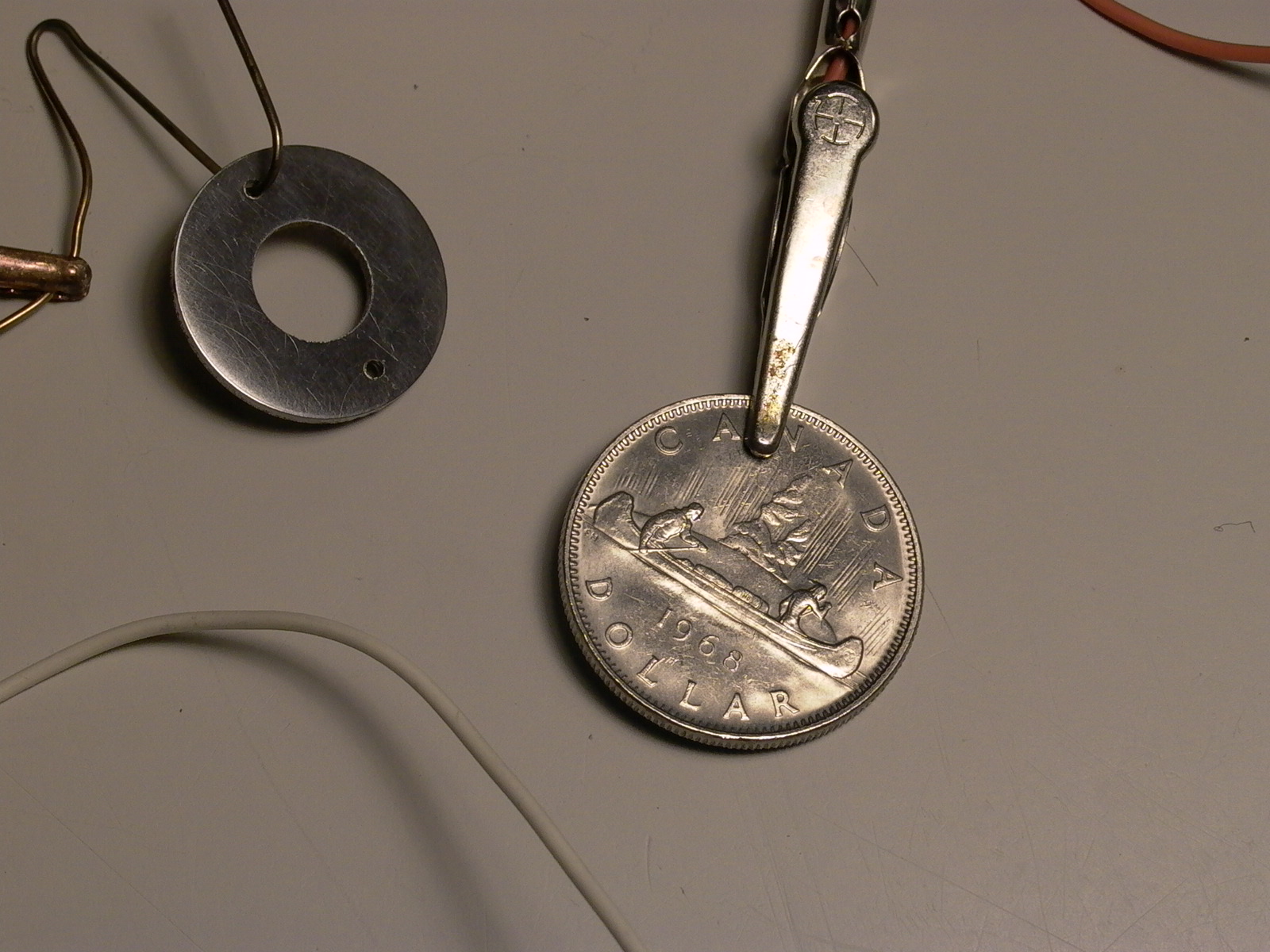
The newly fabricated keyhole escutcheon was then nickel plated to match the other hardware. The nickel coat was applied by electroplating. I used nickel acetate for the electrolyte solution and an older (1968) circulated large Canadian dollar coin (99.9% pure Ni) as the anode (fig. 70), and plated both the keyhole plate and box corners (not shown).
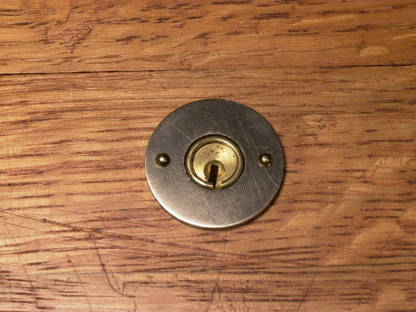
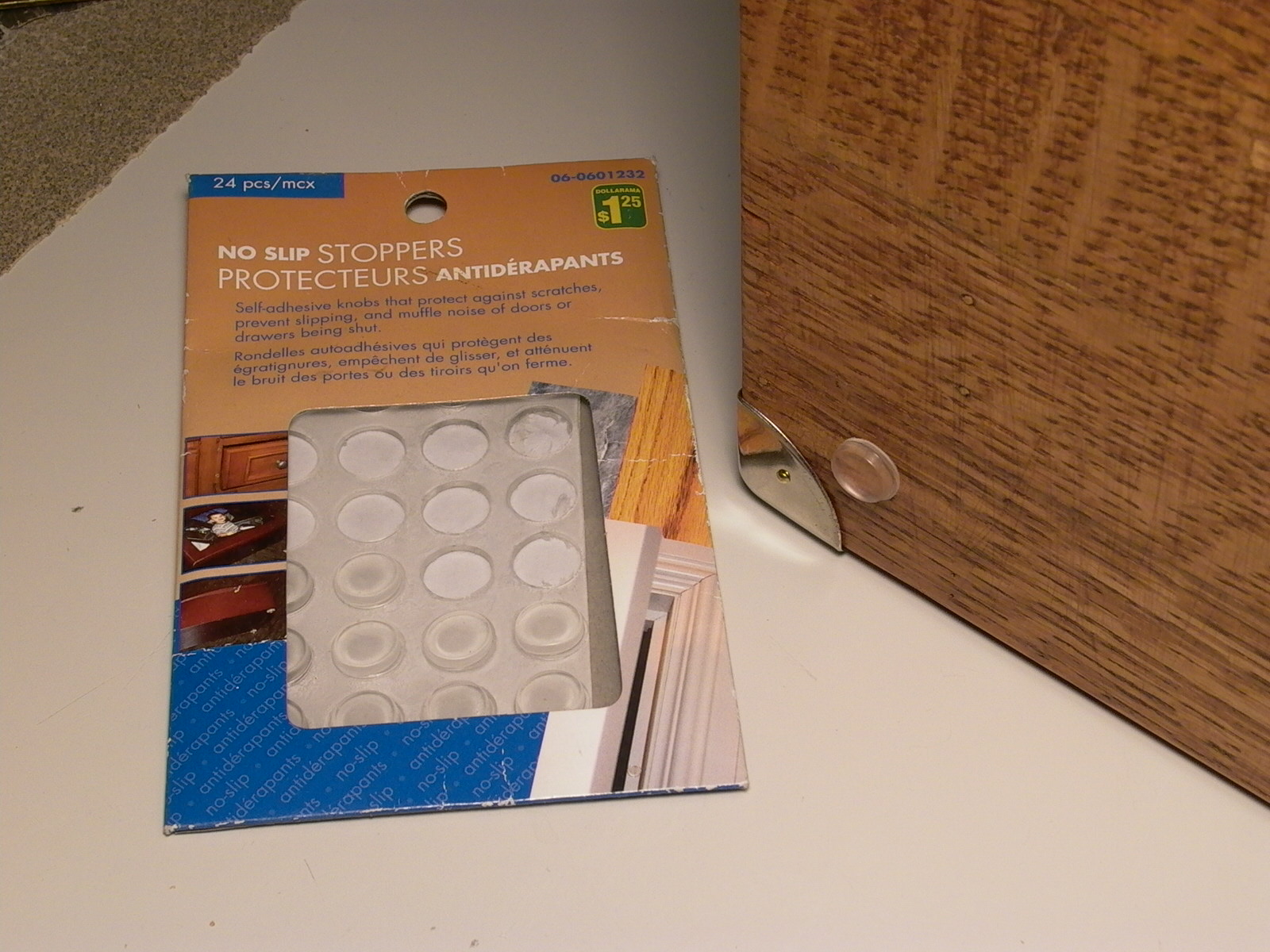
The escutcheon and box corners were then installed with 0.25″ escutcheon pins (fig. 71), and self-adhesive cabinet door/drawer stoppers were added to the bottom and back of the wooden case (fig 72) to prevent the bottom from scratching the surface of furniture. The stick-on stoppers do tend to fall off so keep spares handy in the headset compartment!
A matching nickel plated carrying handle was then added and finally, the crystal set was installed and locked it place by four wood screws in the corner of the panel into the inner ledge of the box. The radio was now ready for testing.
Initial Tests
The first test was to ensure that connections are secure and correct. Continuity was checked with a digital multimeter, and each wire was checked against the circuit diagram (fig. 3).
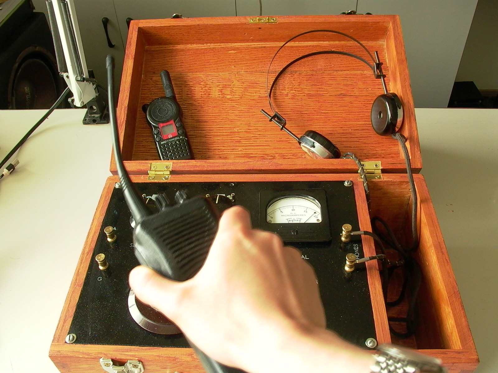
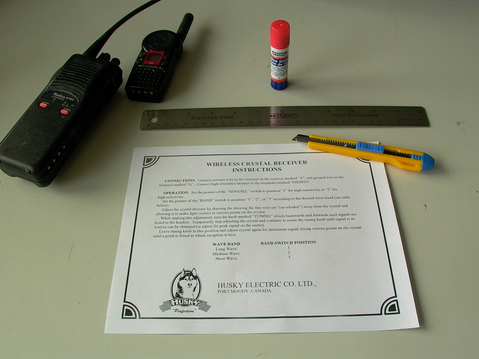
Next, the detectors (diodes) were tested. Because I didn’t have the time or space to set up a long antenna (and by “long”, I mean really LONG; in crystal sets, the antenna does most of the work and relies on efficiency of the design of the radio as there is no amplification), I generated my own signals for the next few series of tests. First, an old 4 watt UHF Motorola Radius P50 2-way radio (walkie-talkie) – reprogrammed to operate on general public FRS/GMRS frequencies – was used as a signal generator. The talk button was pushed and even at a distance of 1 meter away from the crystal set, the signal was too strong, causing to pointer in the Triplett signal meter to deflect to the end of the scale and stuck there (fig. 73).
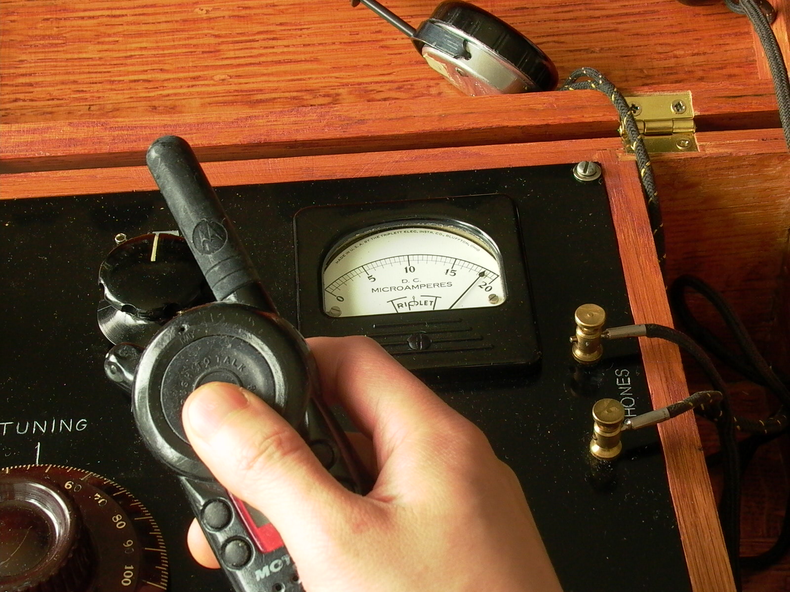
The set was given a shake to loosen the pointer and test was performed again but this time, using a smaller 2-way radio with much less power (1 watt) – a surplus Motorola CLS1810T from a Target store that closed (the CLS1810T is similar to the CLS1410 business band sets but custom-manufactured for use by Target store employees and with their own custom frequencies). With only one watt at 460-something MHz (I have not checked the exact frequency of the Target radio), I was able to work closer in front of the crystal set and get a good deflection on the signal meter. It survived the first test, demonstrating the detector circuit working as expected (fig. 74). I tried on the headphones, pushed the transmit button and heard a click. So far so good.
Of course, 462 MHz is very far from the 0.530-1.710 MHz (530-1710 kHz) used for medium-wave standard AM broadcasting; however, it was the detector that was being tested and not the tuning circuit. Essentially, UHF signals were being forced into the circuit of the crystal radio, bypassing the tuning stage. Also, you will not be able to hear your own voice by talking into the walkie-talkies because modern two-way radios transmit in FM format (even this is could become obsolete soon as digital two-way radios are becoming popular) while the crystal set was designed for signals in AM.
NOTE: Check with the laws of your jurisdiction before conducting similar tests on two-way radio bands (including general public FRS/GMRS frequencies). NEVER interfere with licensed radio services and DO NOT use amateur radio bands for the purpose. Terminate transmissions immediately if asked to stop in any way, especially if told to do so over the radio by a licensed user!
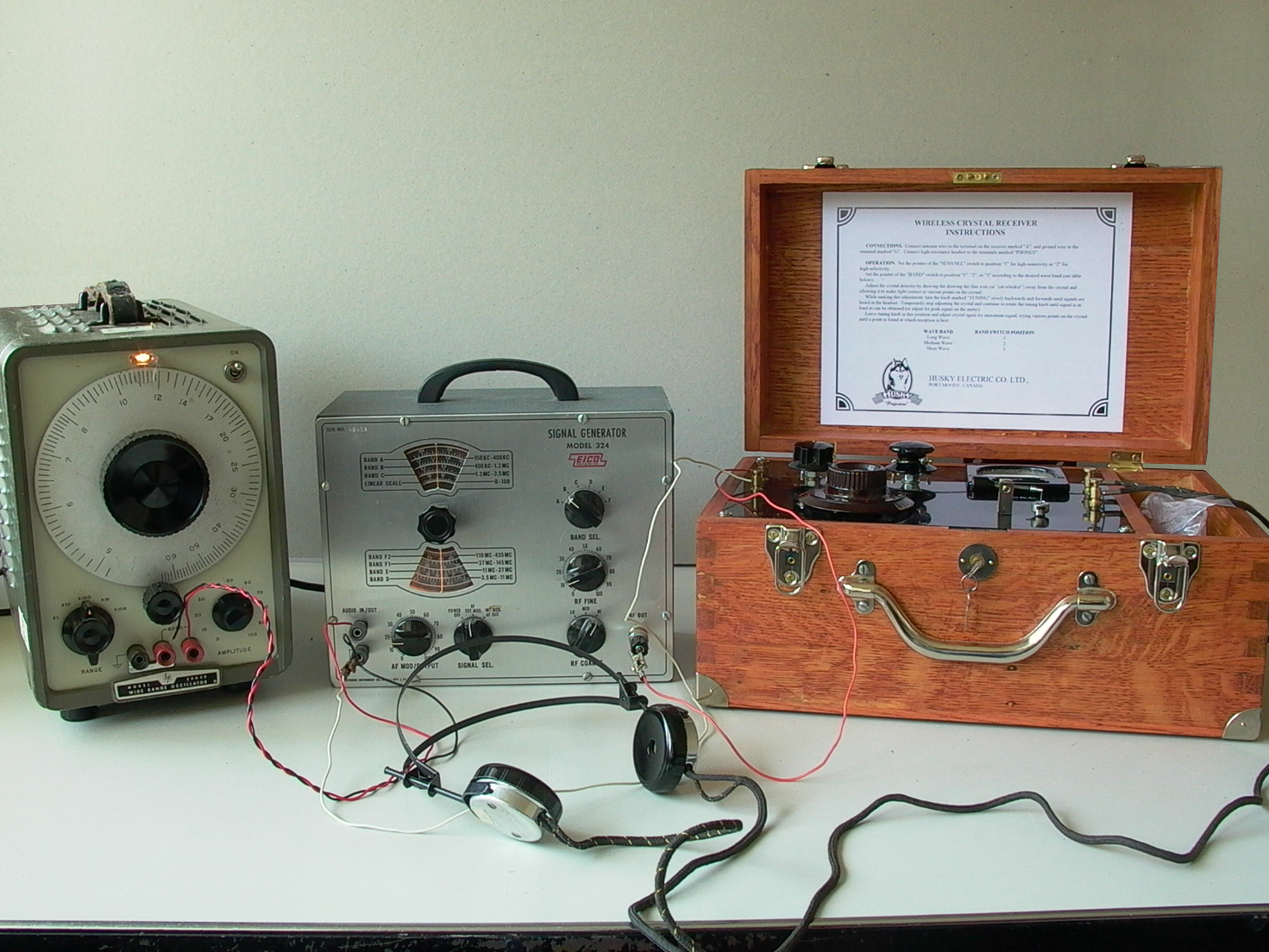
The final test was to actually run an AM signal into the set. I used an Eico 324 RF signal generator to simulate a radio transmission, and a Hewlett Packard audio oscillator (sine wave generator) to modulate the RF in the form of amplitude modulation (AM). I was able to tune-in on the signals and hear the sine wave audio tone through the headphones. On the medium wave band (AM broadcast), the tuning range in the high sensitivity setting was about 400 kc (400 kHz, or 0.400 MHz) to 600 kc (600 kHz, or 0.600 MHz). On the high selectivity setting, the tuning range was 500-1100 kHz (theoretical calculated range is 500-1700 kHz). On the shortwave band, the coverage was aroud 2000 kHz (2.000 MHz) to 3600 kHz (3.600 MHz) in the sensitive position, and 4300-8300 in the high selectivity setting. There discrepancy between real values and theoretical values were huge on the shortwave band, but I don’t plan on using the crystal set as a shortwave receiver so I will leave it at that for now.
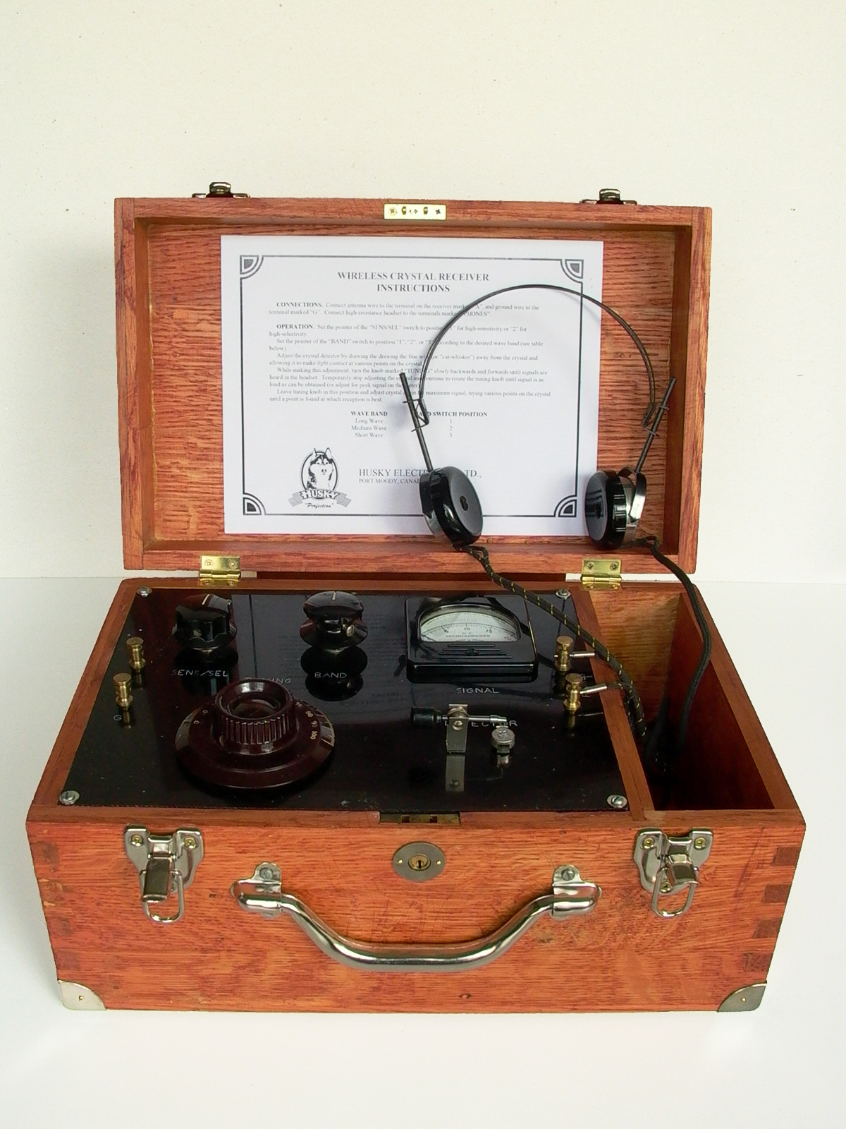
Instruction Sheet
To give the crystal set a factory look, I created an instruction sheet with a logo in Photoshop, printed it with a laser printer, trimmed to size and glued to the inside of the lid with glue stick. As the design of the unit is not a copy of any make/model in particular, I designed my own logo using a fictitious brand name. The husky in the logo is the same dog that was featured in a previous project, now at the age of three years as of this writing. See figures below.


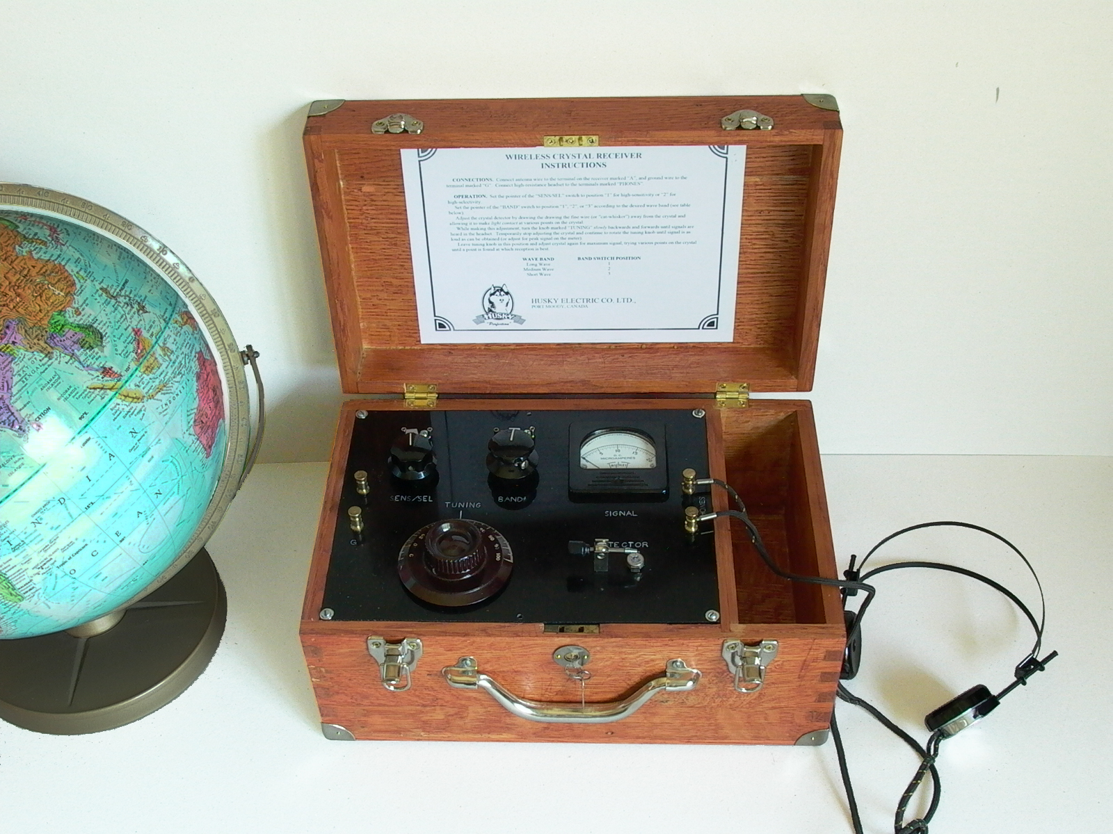
Using the Crystal Set
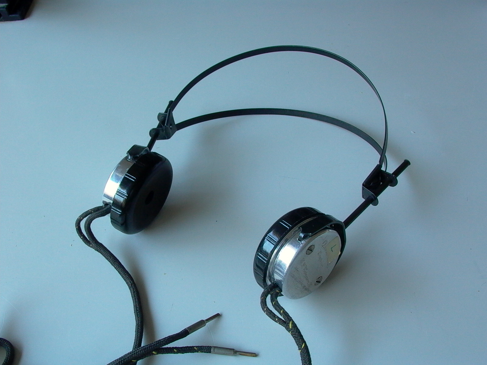
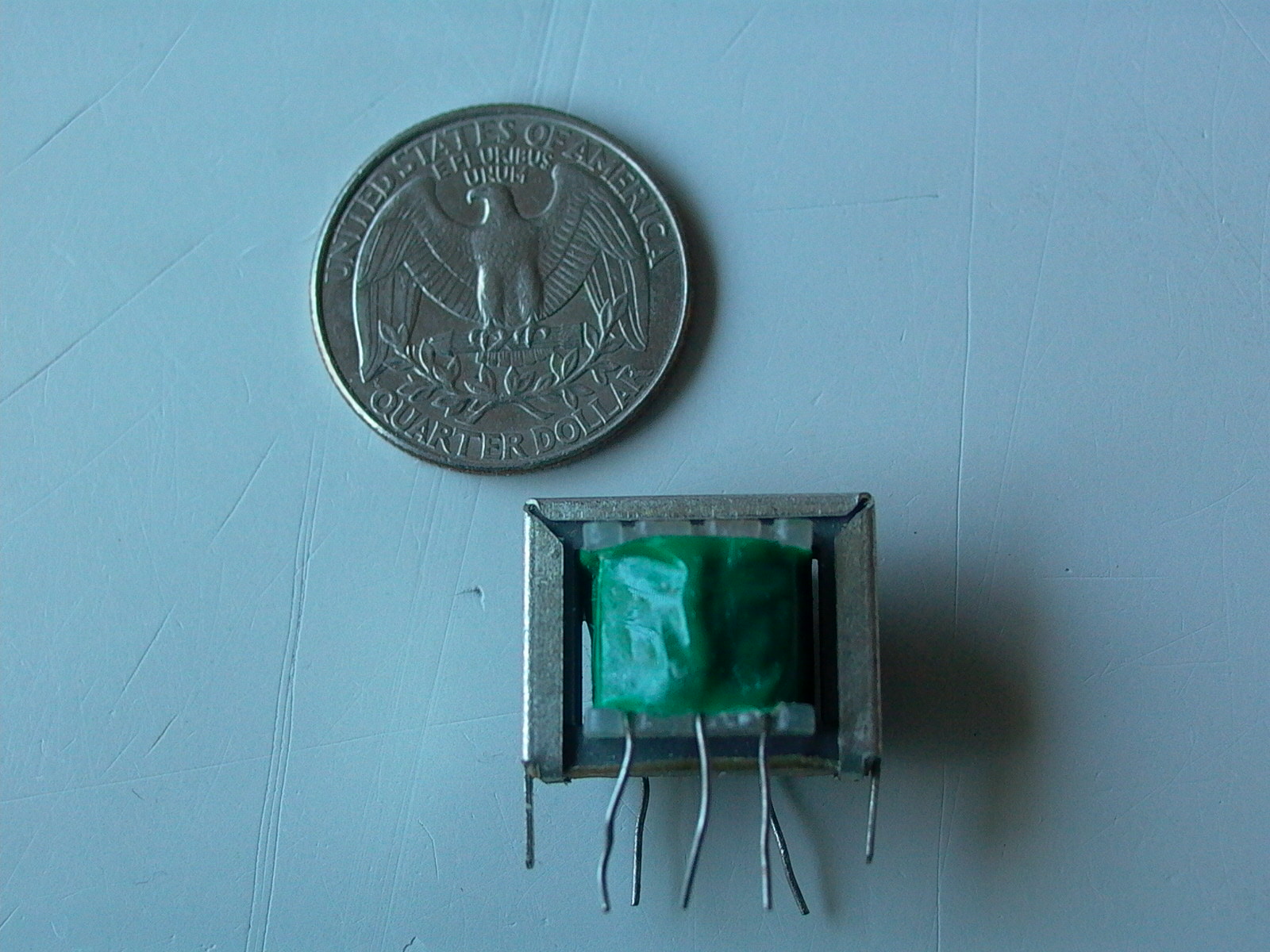
To use a crystal set, a long antenna and good ground connection are required. The ground wire may be connected to a water pipe/faucet or radiator. A pair of 1920’s high impedance headphones are connected to the set for private listening. For use with conventional moderns stereo headphones or earbuds, an impedance matching transformer should be used to covert the high impedance of the output to a lower impedance. A small 500 ohms to 8 ohms or 1200 ohms to 8 ohms audio transformer can be had for around $2-5 apiece, and both may be of use; connect the high-z (symbol for impedance) end of the transformer to the crystal set and the low-z end to a pair of modern earbuds or headset. As I have not tried this, I recommend buying and experimenting with transformers of different z-values.
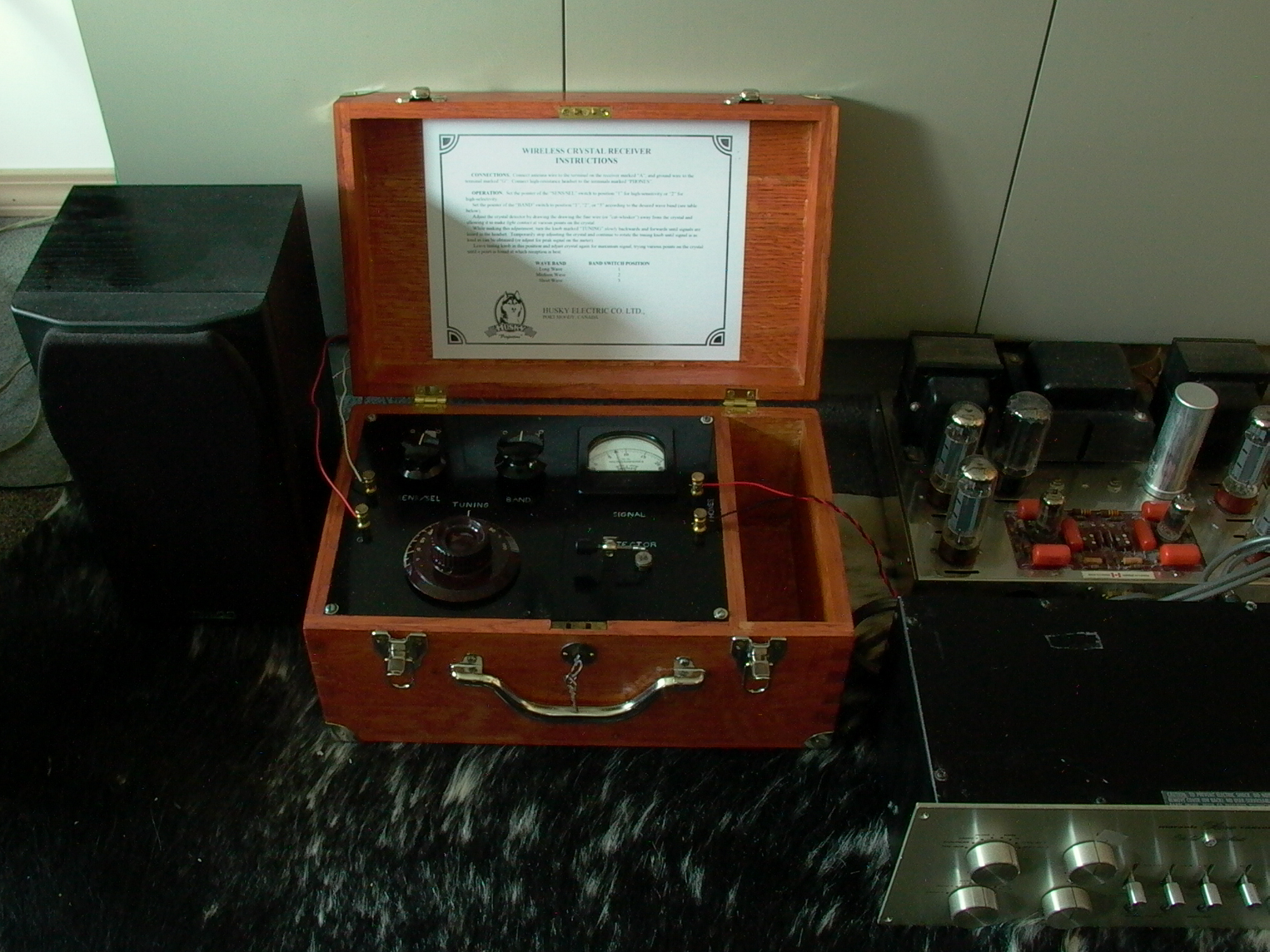
To use the crystal set as a high fidelity receiver, simply connect the headphone output of the unit directly into the line level auxiliary input (“AUX”) of a hi-fi stereo preamp. The rest of the set-up (antenna, ground, etc.) remains unchanged. If you find it necessary to turn the volume up beyond the halfway point, try connecting the crystal set to the phono or tape head input for additional amplification; this may be the case if you are listening to a weak or distant station, or tuning the shortwave band.
Be sure to check out more fun projects and project ideas at http://www.alvenh.com/misc-projects