Top of the Main Case
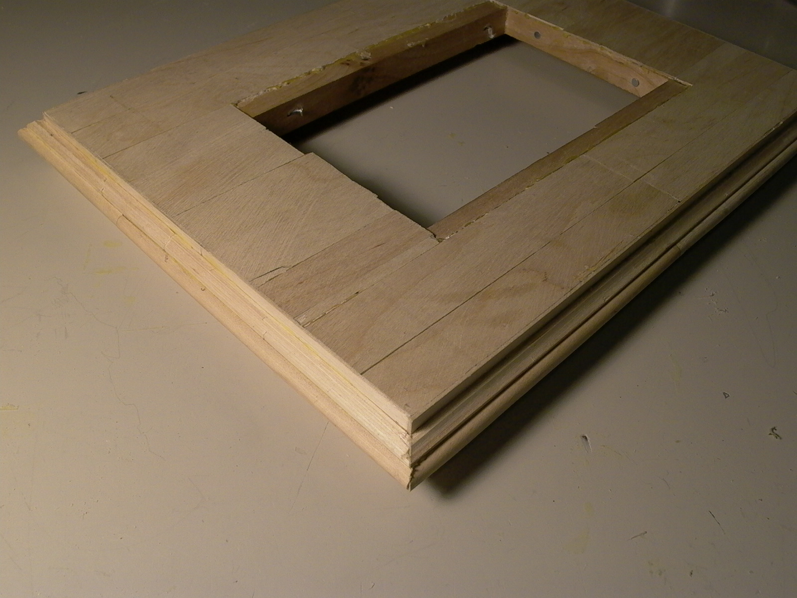
The top of the main body was built in a similar fashion to that of the base, except that scrap oak was used instead of pine for its core and simple butt joints with glue was used. After cutting, planing, and sanding to the right size, thickness and squareness, the entire surface was veneered with jumbo craft sticks to match the wood of the rest of the clock (fig. 77 to 80). The edge was then decorated with a homemade (see next section) glue-on molding.
Making Decorative Molding from Popsicle Sticks
Although this article is not a true tutorial, I have decide to make this section separate from the previous as some readers will, without a doubt, find use for this bit of information in other projects. Artists and photographers who wish to make their own picture frames may find this section handy.
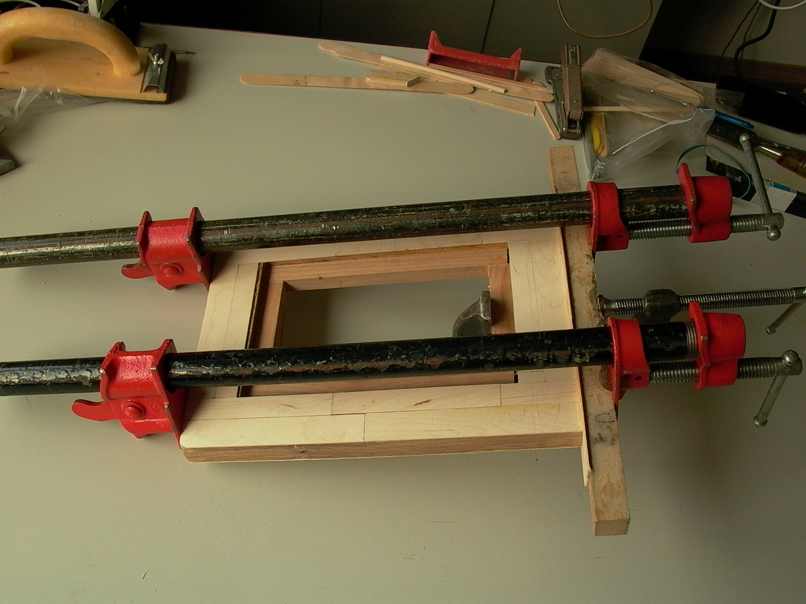
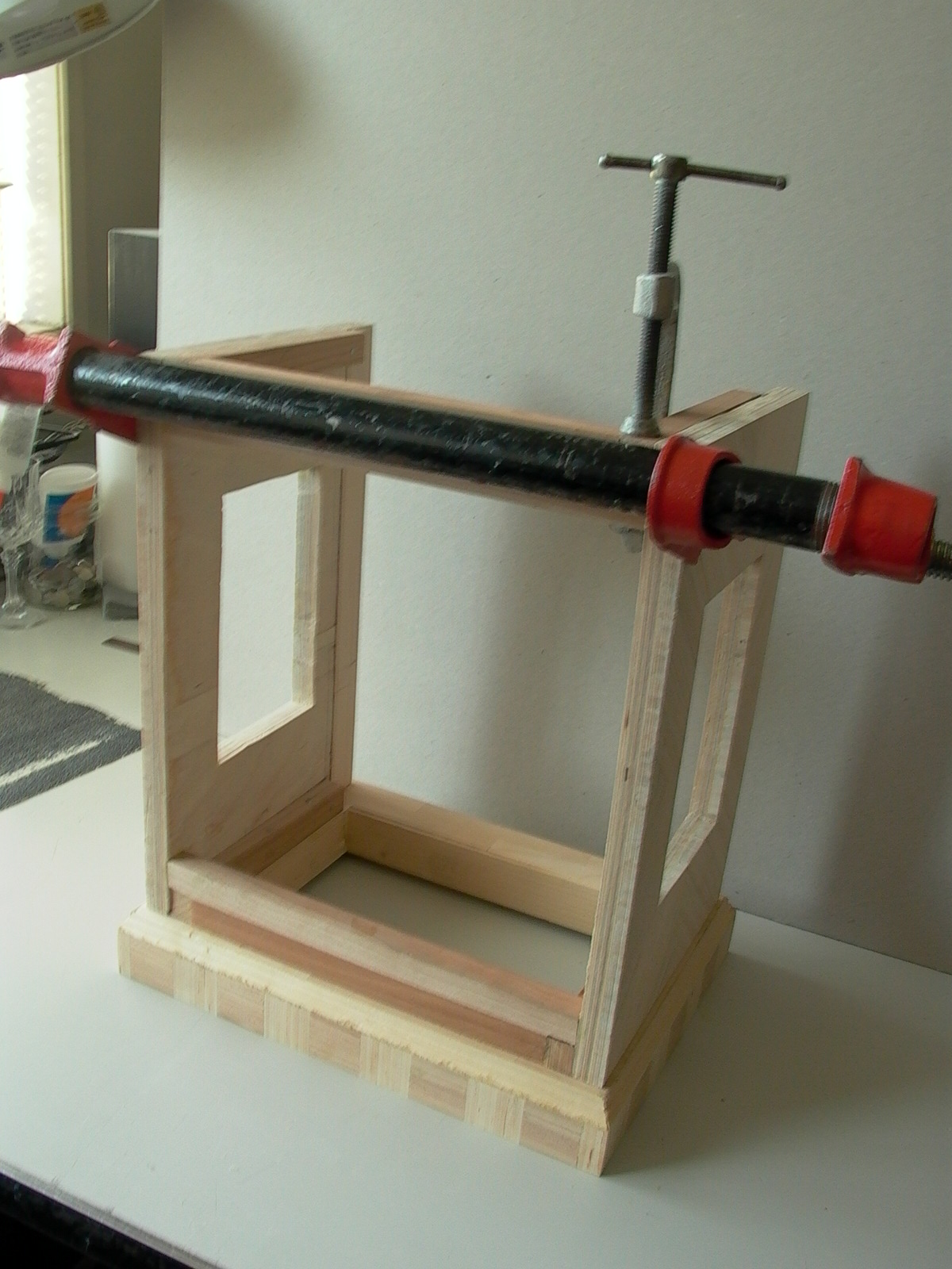
The first step, after deciding how much length to use, a strip of wood was created from craft sticks. The type of craft stick will depend on the required width; one can use either tongue depressors (medium width), Popsicle sticks running in parallel (wider) on as a single strip (thin). In this case (top edge of the case), tongue depressors were used. Rounded edges were trimmed off and glued together end to end (be careful, joints are extremely weak) up to a few inches more that desired length. A straight edge kept the edge of the strips even by pushing the stick edges against the straight edge while gluing. A stack of four strips were then glued, being careful not to allow joints to overlap, and sandwiched between two strips of wood in a drilling vise (fig. 81).
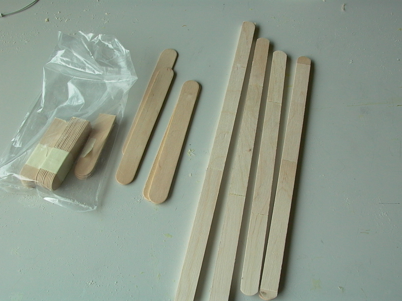
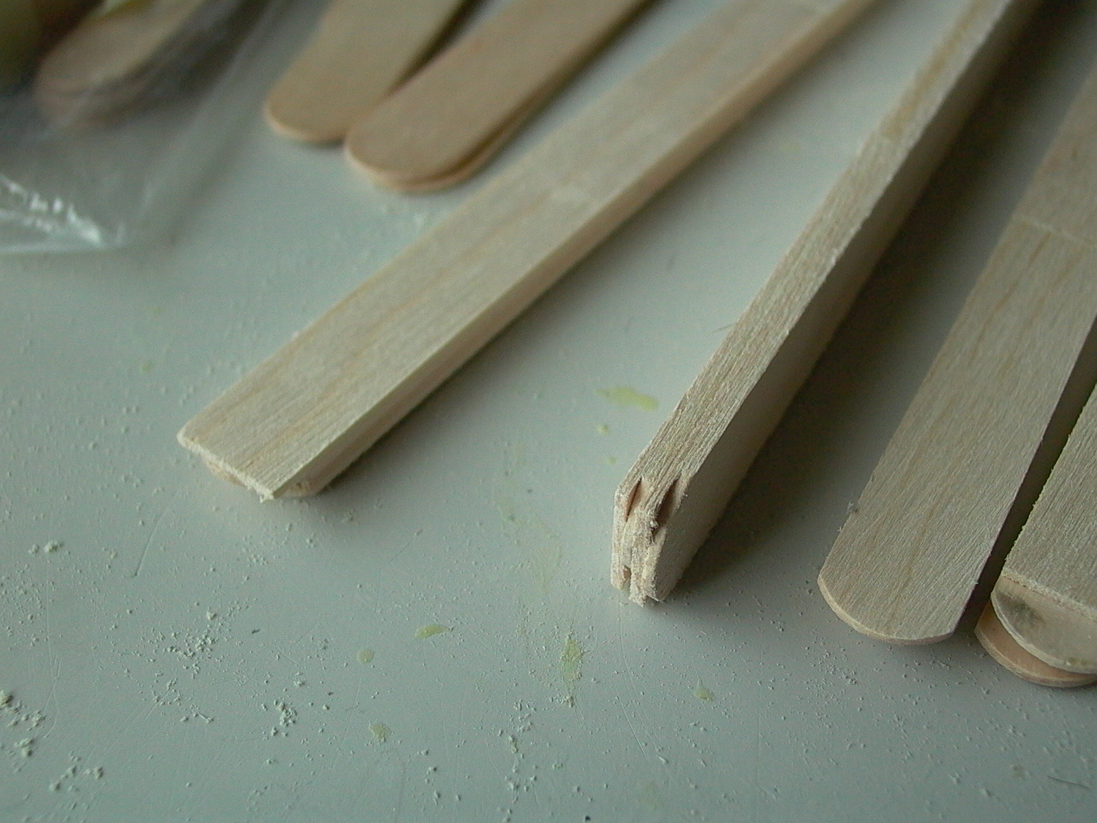
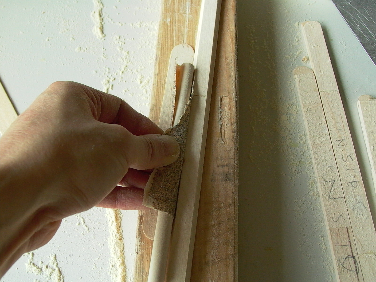
After the glue has dried, edges of the wooden strips were sanded until width was even (fig. 82). The strips were then placed on a flat surface. A piece of P80 sand paper was wrapped around a wooden dowel, then place on a craft stick and slid along the edge back and forth, pressing the sandpaper against the strip. A rounded channel and formed and this was repeat on each side for all strips (fig. 83 and 84).
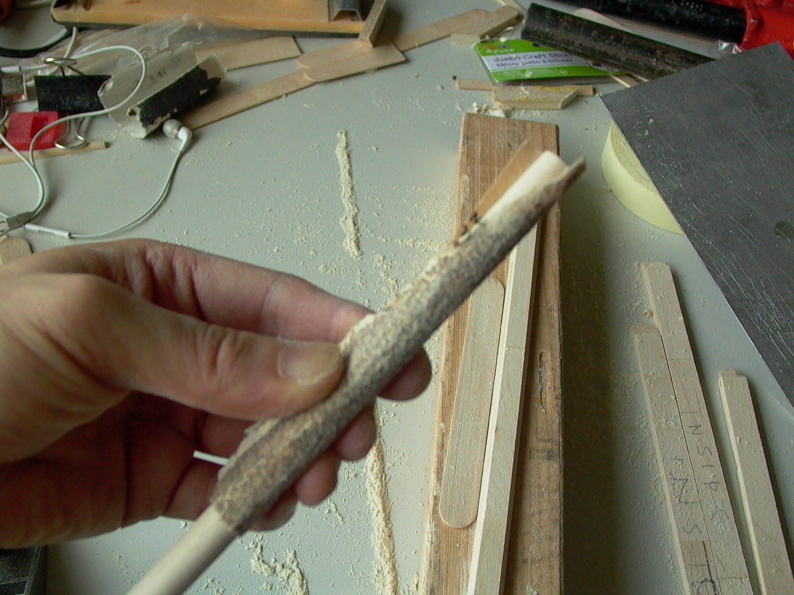
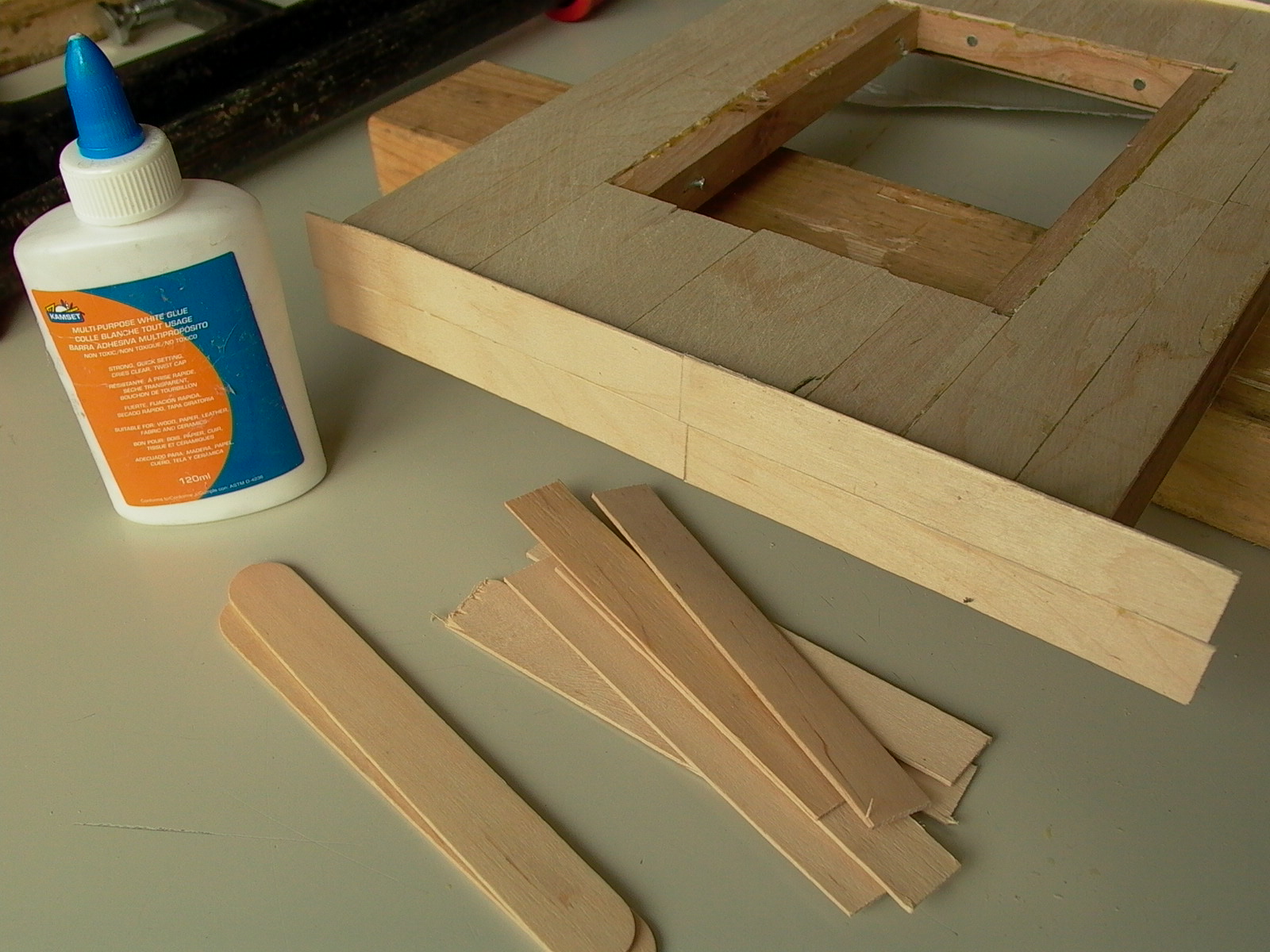
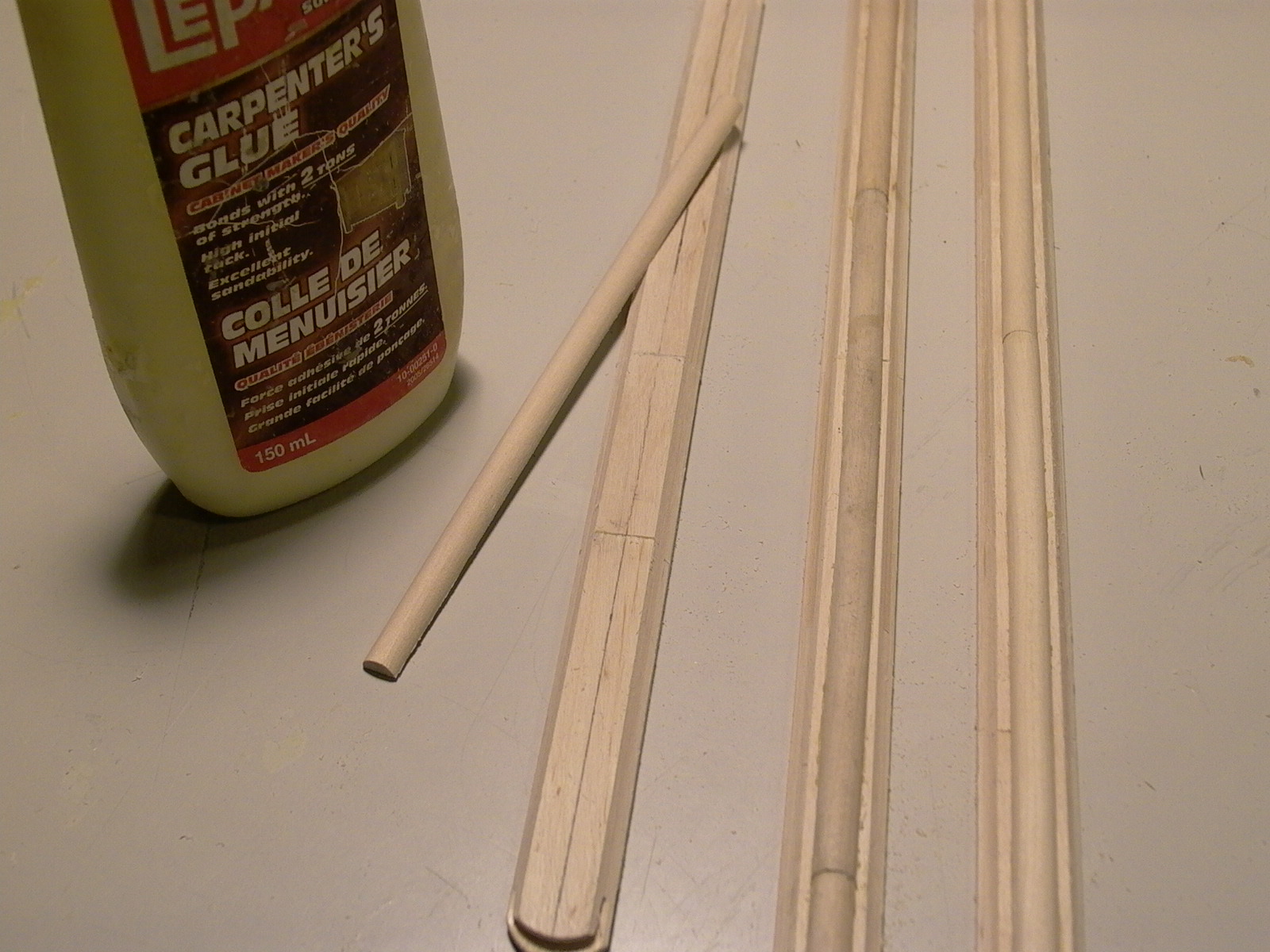
Several wooden dowels were then planed (see pictures in previous section) to form a semicircular cross section, which were then glued along the center of the strips, forming a decorative molding (fig. 85). The “moldings” were then trimmed to size and glued along the edge of the top cover (fig. 86 and 87).
Building the Clock Case
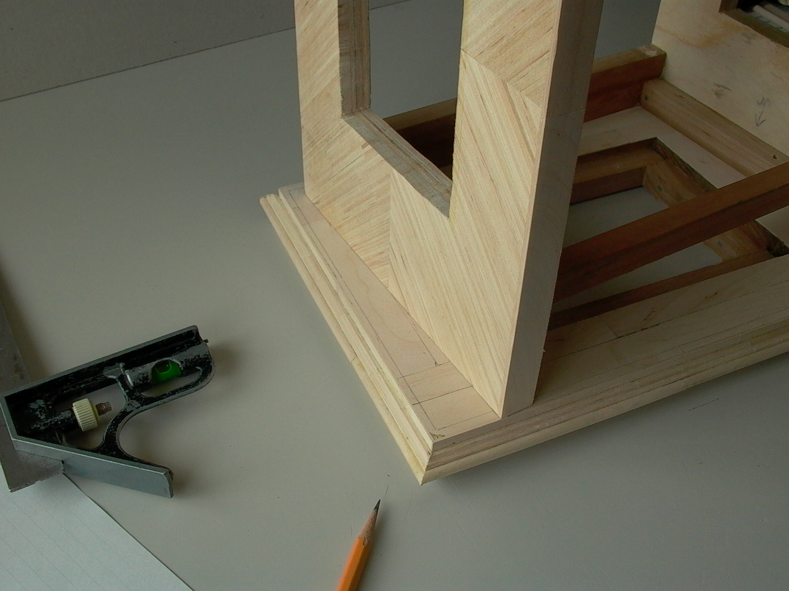
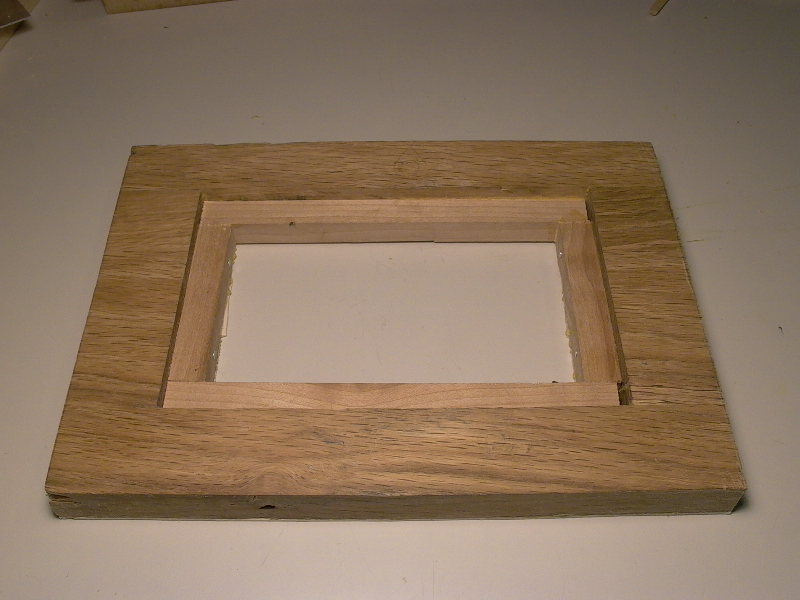
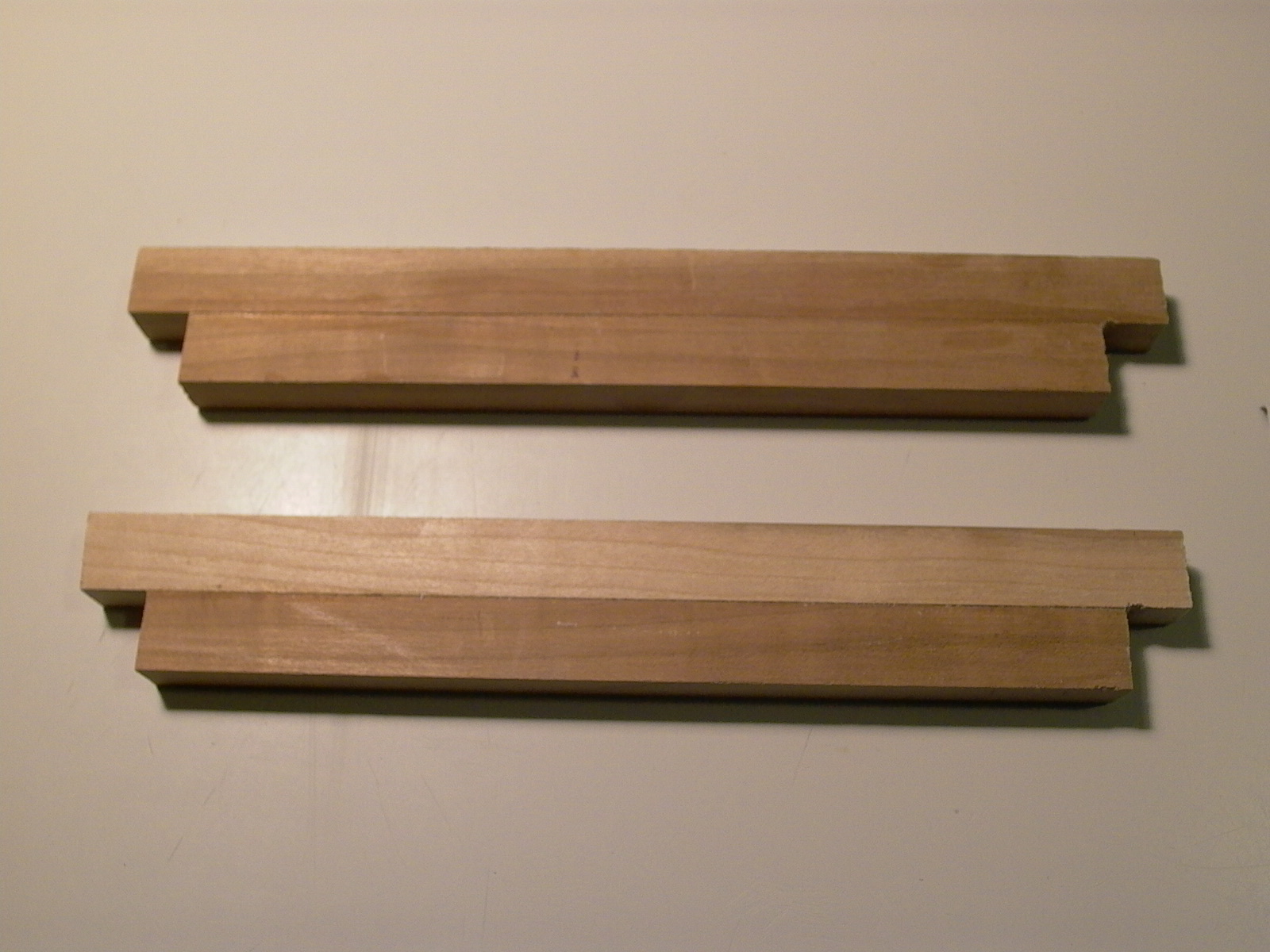
Now that most of the components have been built, it was time to put the case together. The sides were build first using the side boards made in the first step. Before starting it was important to ensure that sides were other measurements were correct.
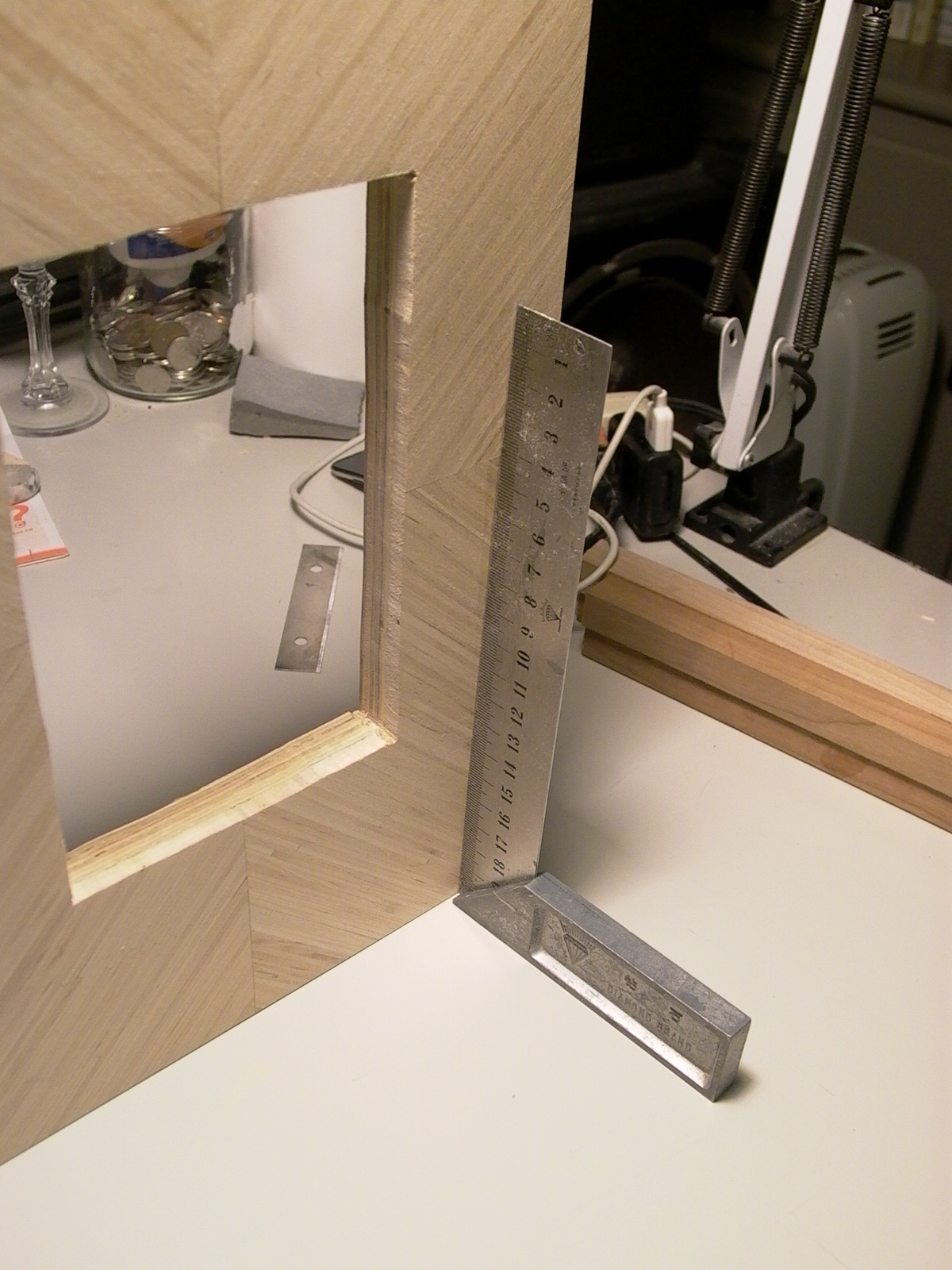
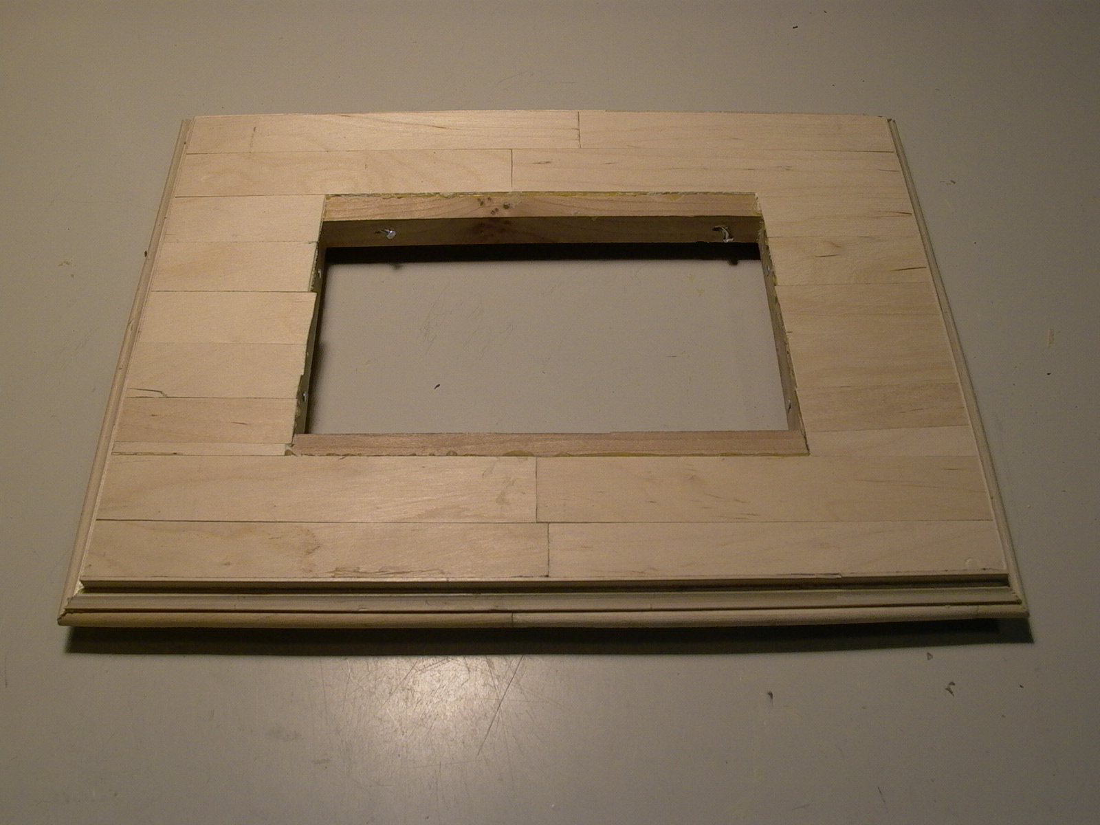
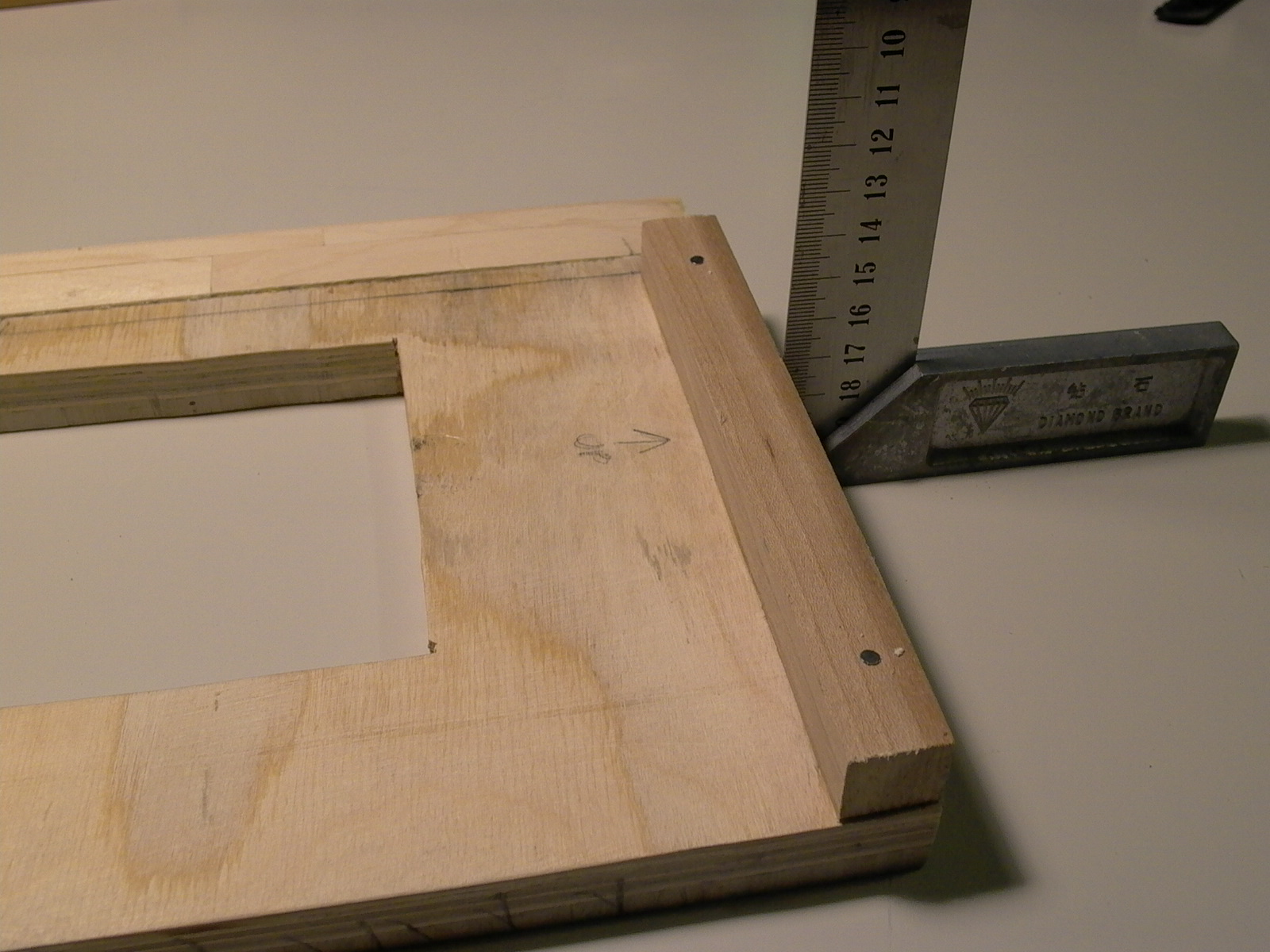
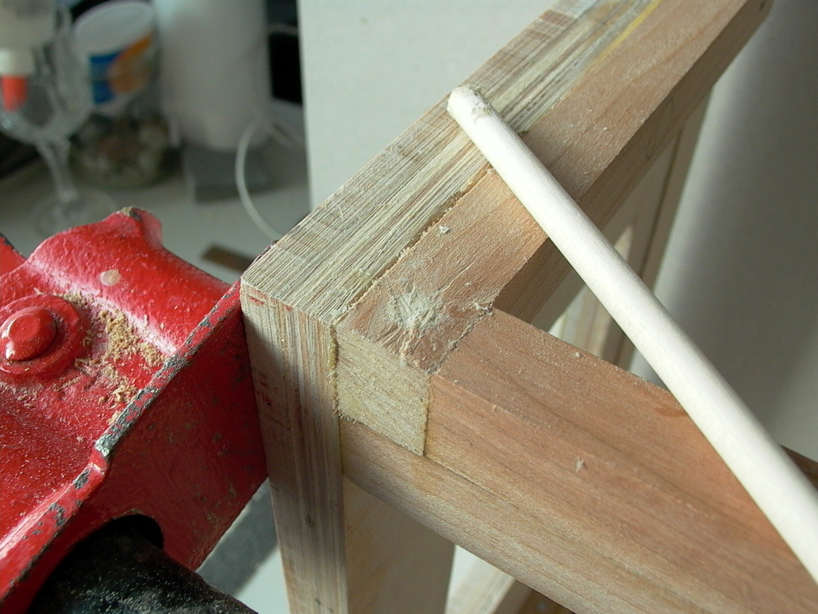
As can be seen from the photo (fig. 88), corners were not perfectly square (the molding around the inner cut-out was commercially made and were not yet glued into place – I have decided NOT to use it later and opted for my own homemade Popsicle stick moldings instead) but the fix was easy. First, a reference edge (“good” edge that will not be cut, shaved, or sanded) was selected, then placed vertically on a table. Shims of scrap wood or craft sticks were glued to one side of the edge that sits on the table so the reference edge was at right angles to the surface of the table (fig. 89).
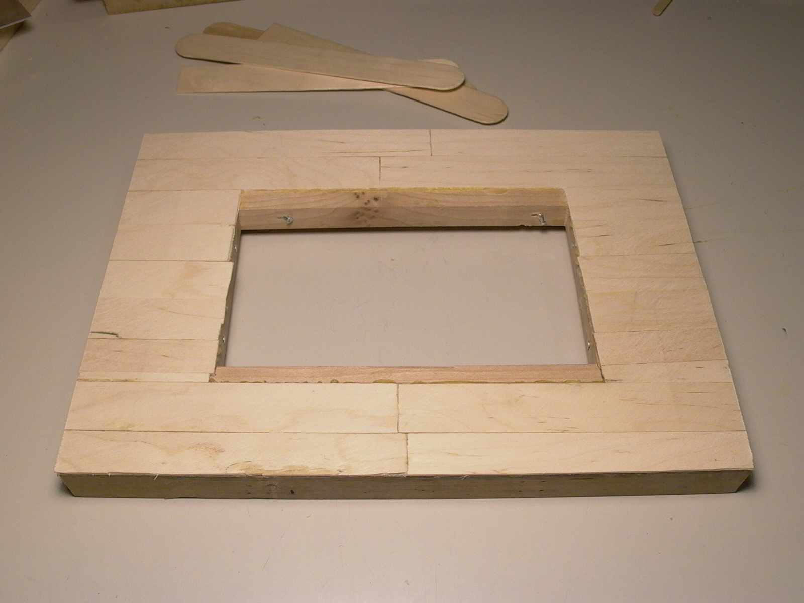
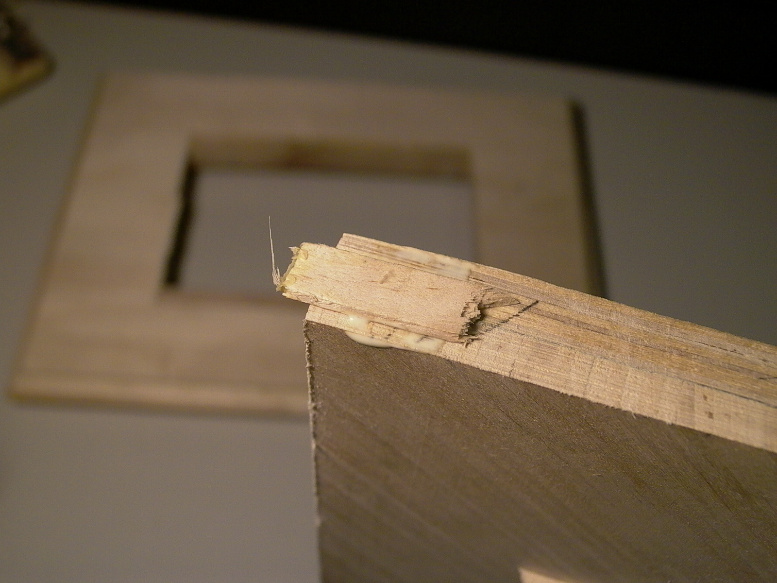
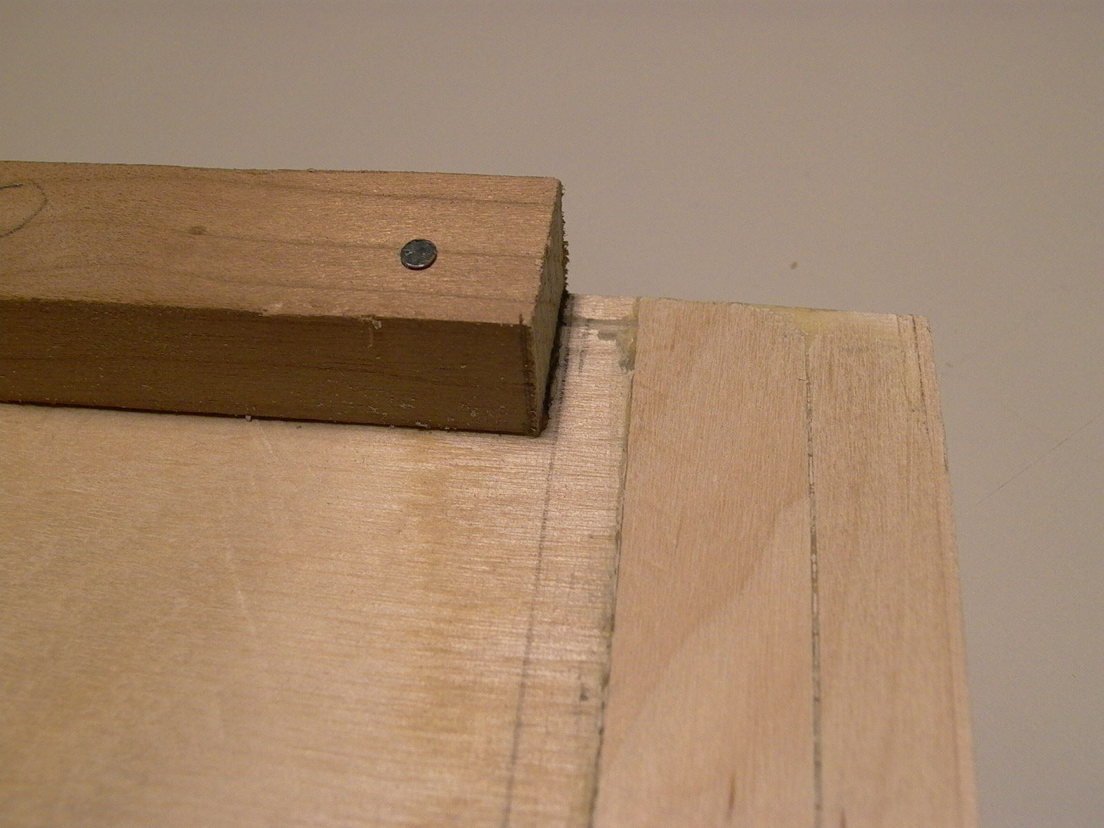
A sheet of P20 (or P36) sandpaper was then clamped to the table, and the edge with the shim was rubbed back and forth on the sandpaper until the shim was complete ground off. It may be a good idea clamp a guide track to the sandpaper to keep the board straight up and perpendicular with the surface (fig. 90). This was repeated wherever necessary until all 8 corners (2 sideboards x 4 corners) were at right angles equal dimensions. After sanding to shape and size, the front and back edges of the side boards were veneered with craft sticks. At the front, the “veneer” wraps around a just a little bit into the inside (fig. 91), leaving a gap between the end of the “veneer” and the end of of the corner piece to allow the front board to slide in (explained later).
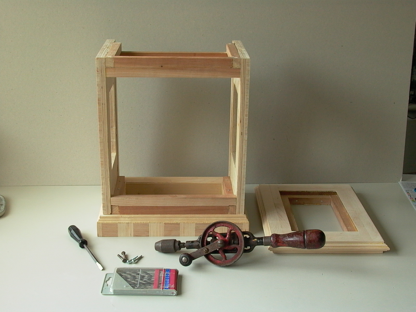
Corner pieces were then glued and nailed to what to be the inside (NOT the patterned side) top and bottom of the side boards (fig. 92). Depending on your design, remember to allow room for the back and front doors, and the front panel onto which the movement and clock dial will be installed (fig. 91)! Mine has a full sized door at the front while the back will use a smaller door; thus, the corner pieces are flush with the back (and will be covered with craft sticks as veneer later).
Next, sideboards were glued and nailed to the base (fig. 93 and 94).
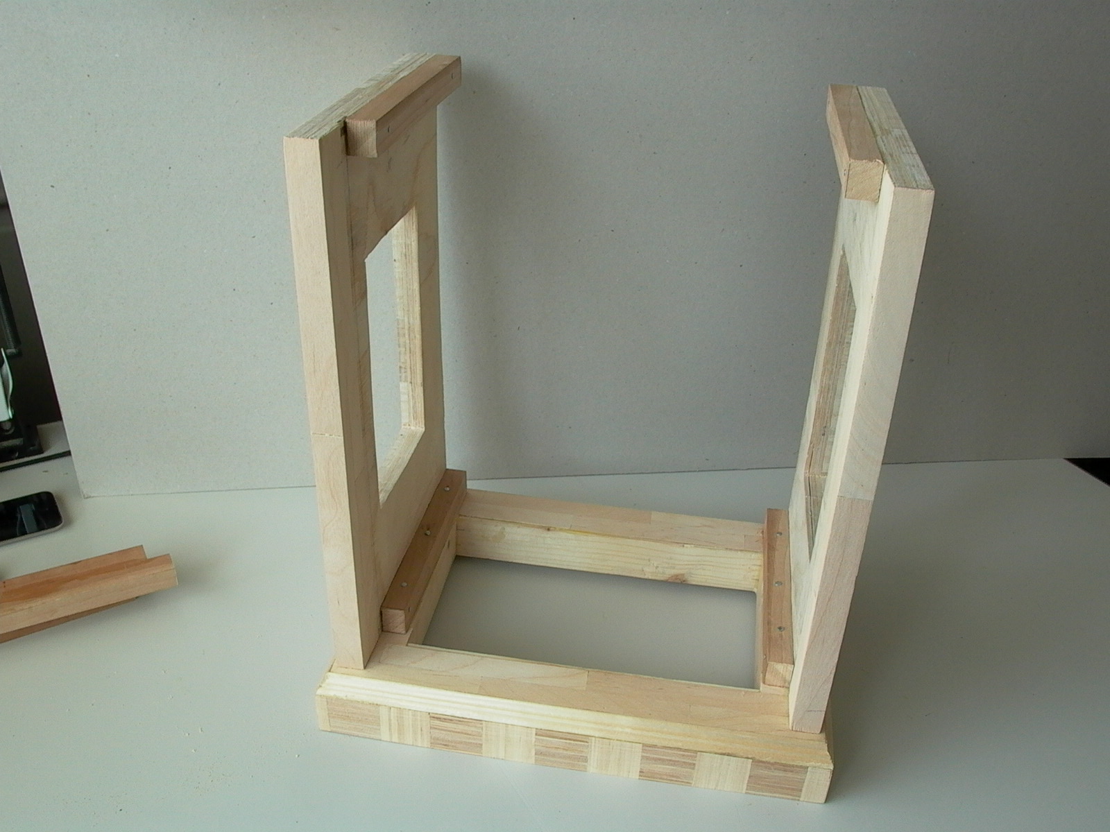
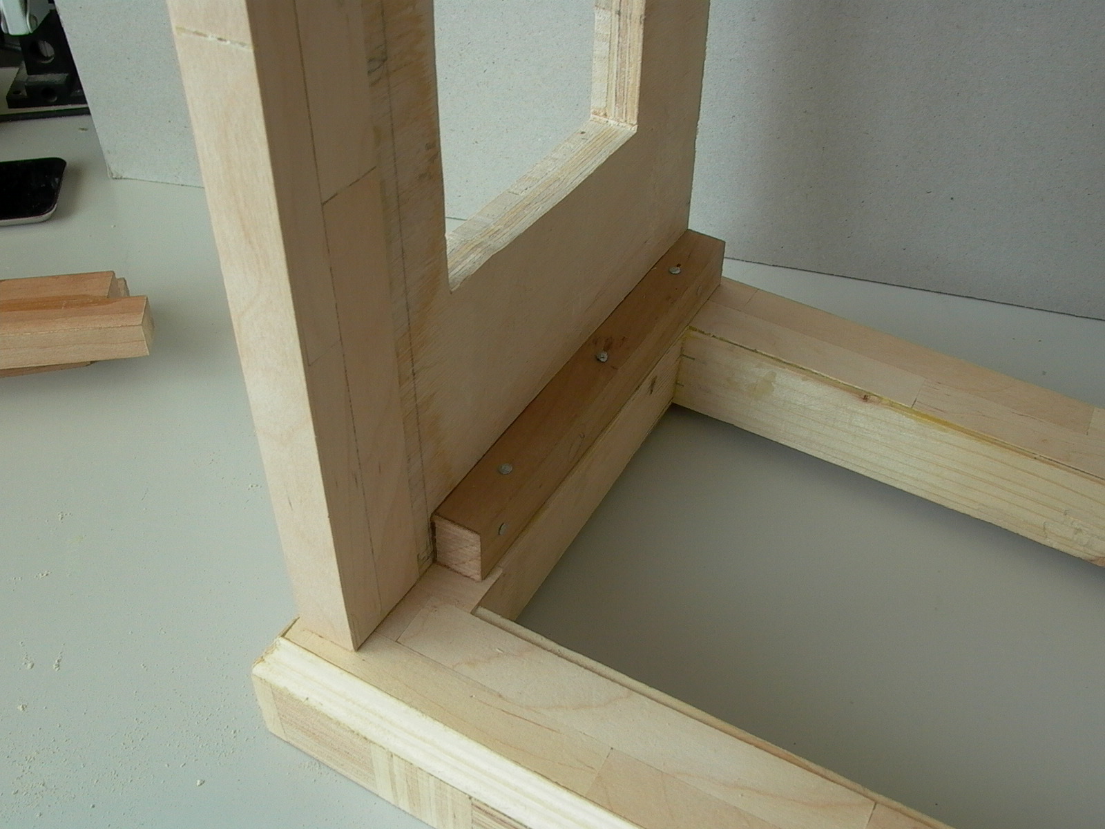
Supports were added to the back (fig. 95-98):
…and front (fig. 99: the case is up-side-down, placed on the top piece):